
Hombre XS Regular Cab 2WD L4-2.2L CPC (1998)
REMOVE OR DISCONNECT
-
Raise the vehicle and support it with safety stands.
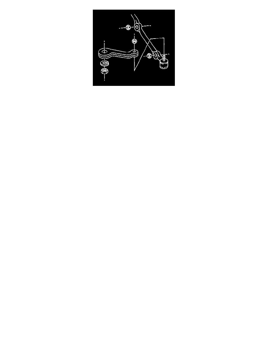
1. Cotter pins and nuts.
2. Outer tie rod ball studs from the steering knuckle using J 6627-A.
NOTICE: Do not attempt to disengage the joint by driving a wedge-type tool between the joint and knuckle. Seal damage could result.
3. Inner tie rod ball studs from the relay rod using J 6627-A.
4. Tie rod ends from the adjuster tube.
-
Loosen the clamp bolts and unscrew the assemblies.
INSPECT
-
Tie rod end for damage.
Tie rod end seals for excessive wear.
-
Threads on the tie rod and tie rod end for damage.
-
Ball stud threads for damage.
-
Adjuster tube for bending or damaged threads.
CLEAN
-
Threads on the ball stud and ball stud nut.
-
The tapered surfaces.
INSTALL OR CONNECT
-
If the tie rod ends were removed, lubricate the tie rod threads with chassis lubricant.
1. Tie rod ends to the adjuster tube. The number of threads on both the inner and outer tie rod ends must be equal within three threads.
2. Inner tie rod ball stud to the relay rod. Make sure the seal is on the stud. Tighten J 29193 or J 29194 to 54 Nm (40 ft. lbs.) to seat the tapers.
Remove the tool.
3. Nut to the inner tie rod ball stud.
Tighten
-
Nut to 47 Nm (35 ft. lbs.).
4. Outer tie rod ball studs to the steering knuckle.
5. Nut.
Tighten
-
Nut to 53 Nm (39 ft. lbs.).
IMPORTANT
-
Advance the nut to align the nut slot with the cotter pin hole. Never back the nut off to align the cotter pin hole.
6. New cotter pin. Spread the cotter pin ends.
-
Lower the vehicle.
ADJUST
-
Toe-in. Refer to Measuring Front Wheel Alignment in Wheel Alignment.