
Hombre XS Space Cab 2WD L4-2.2L CPC (1999)
6. Check current flow direction of the new diode, being sure to install the diode with correct bias. Reference the appropriate service manual wiring
schematic to obtain the correct diode installation position.
7. Attach the new diode to the wire(s) using 60/40 rosin core solder. Before soldering attach some heat sinks (aluminum alligator clips) across the
diode wire ends to protect the diode from excessive heat. Follow the manufacturer's instruction for the soldering equipment.
8. Reinstall terminal(s) into the connector Body if previously removed
9. Tape the diode to the harness or connector using electrical tape.
Important: To prevent shorts to ground and water intrusion, completely cover all exposed wire and diode attachment points with tape.
HO2S Wiring Repairs
NOTE: Do not solder repairs under any circumstances as this could result in the air reference being obstructed.
If the heated oxygen sensor pigtail wiring, connector,or terminal is damaged the entire oxygen sensor assembly must be replaced. Do not attempt to
repair the wiring, connector, or terminals. In order for the sensor to function properly it must have a clean air reference. This clean air reference is
obtained by way of the oxygen sensor signal and heater wires. Any attempt to repair the wires, connectors or terminals could result in the obstruction of
the air reference and degrade oxygen sensor performance.
The following guidelines should be used when servicing the heated Oxygen Sensor:
-
Do not apply contact cleaner or other materials to the sensor or vehicle harness connectors. These materials may get into the sensor, causing poor
performance. Also, the sensor pigtail and harness wires must not be damaged in such a way that the wires inside are exposed. This could provide a
path for foreign materials to enter the sensor and cause performance problems.
-
Neither the sensor nor vehicle lead wires should be bent sharply or kinked. Sharp bends, kinks, etc., could block the reference air path through the
lead wire.
-
Do not remove or defeat the oxygen sensor ground wire (where applicable). Vehicles that utilize the ground wire sensor may rely on this ground as
the only ground contact to the sensor. Removal of the ground wire will also cause poor engine performance.
-
To prevent damage due to water intrusion, be sure that the peripheral seal remains intact on the vehicle harness connector.
The engine harness may be repaired using the J 38125-B.
SIR Wiring Repairs
J 38125-B Terminal Repair kit
Important: Refer to Wiring Repairs in order to determine the correct wire size for the circuit being repaired. Using the correct wire size ensures that
circuit integrity is not compromised.
If any wire except the pigtail is damaged, repair the wire by splicing in a new section of wire of the same gauge size (0.5 mm, 0.8 mm, 1.0 mm, etc.).
Use the sealed splices and splice crimping tool from the J 38125-B. Use the following wiring repair procedures to ensure the integrity of the sealed
splice.
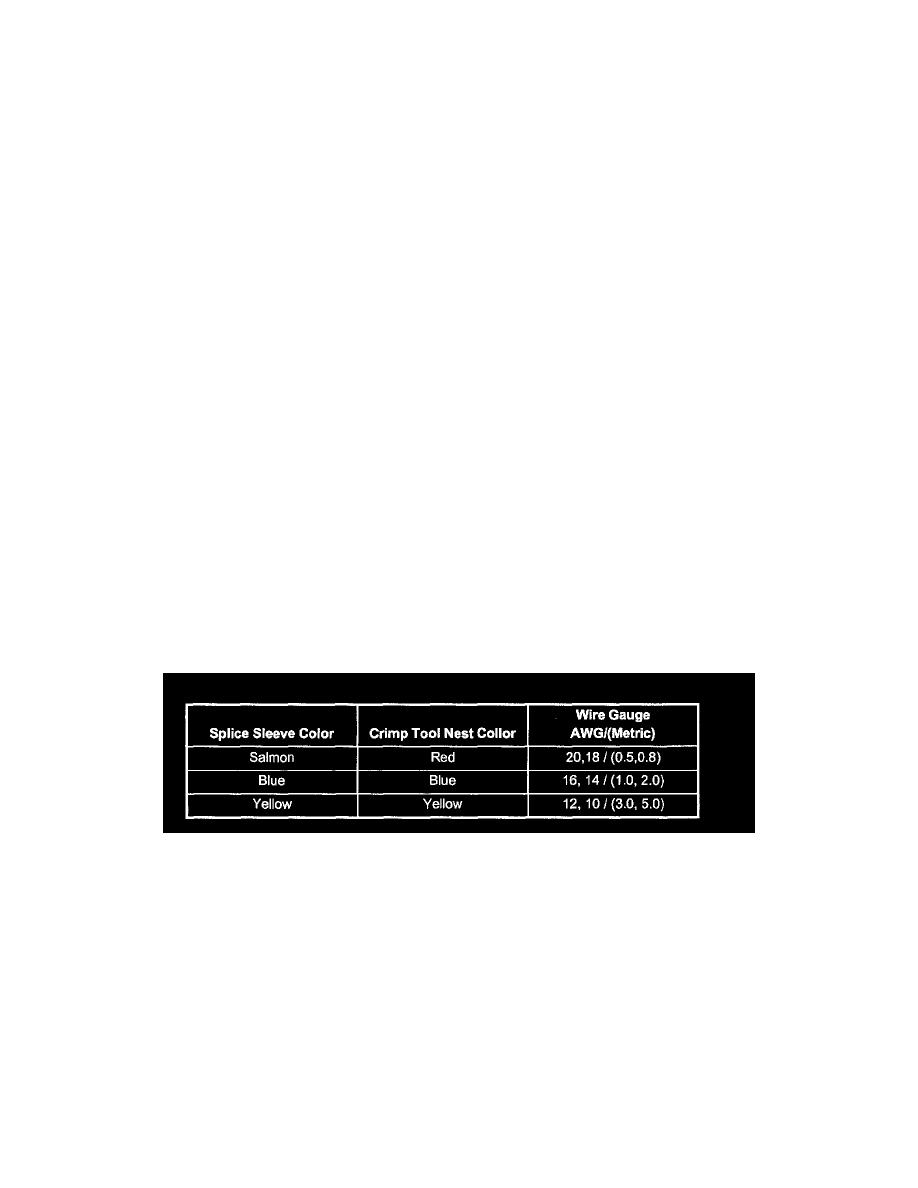
Crimp And Seal Splice Table
Important: Perform the following procedures in the listed order. Repeat the procedure if any wire strands are damaged.
1. Open the harness by removing any tape.
To avoid wire insulation damage use a sewing seam ripper (available from sewing supply stores) to cut open the harness.
2. Cut the wire.
-
Cut as little wire OFF the harness as possible. The extra length of wire may be needed to change the location of a splice.
-
Ensure that each splice is at least 40 mm (1.5 in) away from other splices,harness branches and connectors. This helps prevent moisture from
bridging adjacent splices and causing damage.
3. Select the proper size and type of wire.
-
The wire must be of equal or greater size than the original.
-
To find the correct wire size do one of the following:
-
Find the wire on the schematic and convert the metric size to the equivalent AWG size.
-
Use an AWG wire gauge.
-
If unsure of the wire size, begin with the largest opening in the wire stripper and work down until achieving a clean strip of the insulation.
-
The wire's insulation must have the same or higher temperature rating.