
Hombre XS Space Cab 2WD L4-2.2L CPC (1999)
Engine Control Module: Component Tests and General Diagnostics
PCM Outputs Diagnosis
Diagnosis
The following table will diagnose the PCM controlled outputs from the output driver modules only. For diagnosis of the cruise control module circuit,
refer to Cruise Control Diagnosis. For specific system components and wiring refer to Electrical Diagnosis or Transmission Diagnosis for transmission
related components.
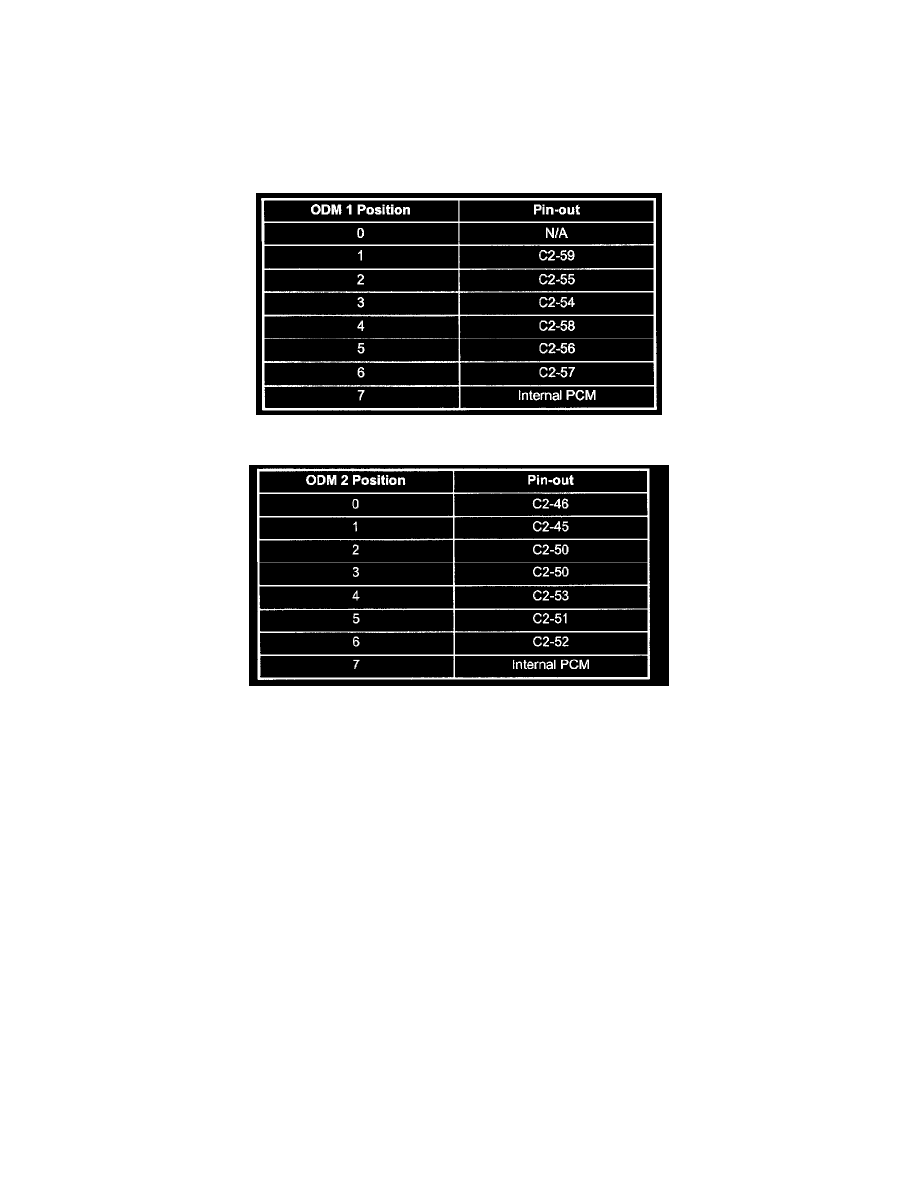
Output Driver 1
Output Driver 2
Circuit Description
The Powertrain Control Module (PCM) controls most components with electronic switches which complete a ground circuit when turned ON. These
switches are arranged in groups of 4 and 7, and are called either a surface mounted quad driver module, which can independently control up to 4 outputs
(PCM) terminals or an Output Driver Module (ODM), which can independently control up to 7 outputs. Not all outputs are always used.
Drivers are fault protected. If a relay or solenoid is shorted, having very low or zero resistance, or if the control side of the circuit is shorted to voltage, it
would allow too much current flow into the PCM. The driver senses this and the output is turned OFF or its internal resistance increases to limit current
flow and protect the PCM and driver. The result is high output terminal voltage when it should be low. If the circuit from B+ to the component or the
component is open, or the control side of the circuit is shorted to ground, terminal voltage will be low. Either of these conditions is considered to be a
driver fault.
Drivers also have a fault line to indicate the presence of a current fault to the PCM's central processor. A scan tool displays the status of the driver fault
lines as 0 = OK, 1 = Fault. In order to correctly read the Short or Open PCM Output parameters on the scan tool, the ODM positions read from left to
right: 7, 6, 5, 4, 3, 2, 1, 0. The actual pin-out locations for the bits are shown on the following tables:
Refer to Schematics for applicable pin-outs.
Diagnostic Aids
-
The scan tool has the ability to command certain components and functions ON and OFF. If a component or function does not have this
capability, operate the vehicle during its normal function criteria to check for an open or shorted circuit.
-
An open or short to ground will appear in the open positions on the scan tool only when it is not commanded by the PCM or scan tool, while a
short to voltage will appear in the short positions on the scan tool only while the component is being commanded by the PCM or scan tool.