
Hombre XS Space Cab 2WD V6-4.3L (1998)
Hydraulic Control Assembly - Antilock Brakes: Service and Repair
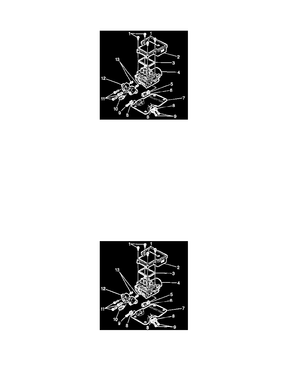
Removal and Installation
REMOVAL PROCEDURE
1. Remove the two fuse block mounting bolts from
2. Disconnect the electrical connector from the combination valve (12).
3. Remove the front and rear brake pipes (from master cylinder) from the combination valve.
4. Remove the right front, left front and rear brake pipes from the tube adapters (6).
5. Remove the four 10mm bolts (9) that fasten the EHCU bracket (7) to the vehicle mounting bracket.
6. Lift the EHCU partially out or the engine compartment.
7. Disconnect the four electrical connectors from EBCM (2).
8. Fully remove the EHCU from the vehicle.
9. Remove the three alien bolts (11) from the combination valve (12).
10. Remove the combination valve (12).
IMPORTANT: Do not reuse the transfer tubes. Always install new transfer tubes.
11. Remove the two transfer tubes (13).
12. Remove the three 13 mm bolts (0) that fasten the bracket to the BPMV.
13. Remove the four T-25 Torx bolts (1) from the EBCM.
IMPORTANT: Do not use a tool to pry the EBCM or the BPMV. Excessive force will damage the EBCM.
14. Remove the EBCM (2) from the BPMV (4). Removal may require a light amount of force.
INSTALLATION PROCEDURE
1. Install the new transfer tubes (10) into the combination valve into the combination valve (9).
2. Install the combination valve onto the BPMV(4)
3. Install the three alien bolts (8) that fasten the combination valve (9) to the BPMV(4).