
Hombre XS Space Cab 2WD V6-4.3L (1998)
Sensing And Diagnostic Module: Component Tests and General Diagnostics
Circuit Description
When the supplemental restraint Sensing and Diagnostic Module (SDM) recognizes IGNITION 1 voltage, applied to terminal 10, is greater than 8.2
volts, the SDM flashes the AIR BAG warning lamp seven times to verify operation. At this time the 5DM performs POWER-ON tests followed by the
RESISTANCE MEASUREMENT test and the CONTINUOUS MONITORING tests. Upon detection of a malfunction, the SDM sets a current
Diagnostic Trouble Code (DTC) and illuminates the AIR BAG warning lamp. The SDM will clear current DTCs and preserve them in a history file
when:
- The malfunction is no longer detected.
- The ignition switch is cycled.
This does not include DTCs B1O18, B1024, B1051, B1053, and B1071. DTCs B1O18, B1024, B1051, B1053 are latched codes. You cannot clear a
latched code. DTC B1071 may not clear after you issue a clear codes command.
Important: Repair the malfunction that set the DTC before you replace the SDM.
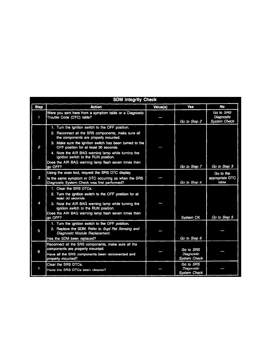
SRS Integrity Check
Test Description
The numbers below refer to the step numbers on the diagnostic table:
2. This test confirms a circuit malfunction. If no current malfunction is occurring (history DTC set), refer to the diagnostic aids for the appropriate
DTC table as indicated through the scan tool. Do not replace the supplemental restraint Sensing and Diagnostic Module (SDM) for a history DTC
other than DTC B1071.
3. This test checks for a malfunction introduced into the SRS during the diagnostic process. It is unlikely that a malfunctioning SDM would cause a
new malfunction to occur during this process.