
Hombre XS Space Cab 2WD V6-4.3L (1998)
Removing Turn Signal And Multifunction Switch
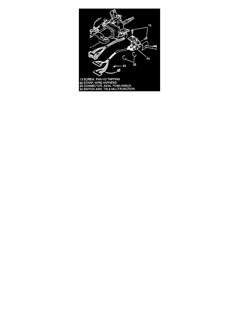
9. Two wire harness straps (22) from steering column wire harness.
10. Steering column bulkhead connector from vehicle wire harness.
11. Axial position assurance connector (23) from electrical (BTSI) actuator (61). (column shift only)
-
Electrical connector from (BTSI) actuator (61).
12. Grey and black connectors of turn signal & multi-function switch (24) from column bulkhead connector.
13. Two pan head tapping screws (13).
14. Turn signal & multifunction switch assembly (24) from column.
Install or Connect
CAUTION: Always use the correct fastener in the proper location. When you replace a fastener, use ONLY the exact part number for that application.
ISUZU will call out those fasteners that require a replacement after removal. ISUZU will also call out the fasteners that require thread lockers or thread
sealant. UNLESS OTHERWISE SPECIFIED, do not use supplemental coatings (Paints, greases, or other corrosion inhibitors) on threaded fasteners or
fastener joint interfaces. Generally, such coatings adversely affect the fastener torque and the joint clamping force, and may damage the fastener. When
you install fasteners, use the correct tightening sequence and specifications. Following these instructions can help you avoid damage to parts and
systems.
1. Turn signal & multifunction switch assembly (24) to column.
-
With small blade screwdriver compress electrical contact and move multi-function switch (24) into position.
-
Electrical contact must rest on cancelling cam assembly (6).
2. Two pan head tapping screws (13). Tighten screws (13) to 7 Nm (62 lb.in.).
3. Grey and black connectors of multi-function switch (24) to column bulkhead connector.
4. Electrical connector to electrical (BTSI) actuator (61). (Column shift only)
-
Axial position assurance connector (23).
5. Steering column bulkhead connector to vehicle wire harness.
6. Two wire harness straps (22) to steering column wire harness.
7. Install the upper shroud.
8. Two torx head screws to upper shroud. Tighten screws to 1.5 N.m (13 lb.in.).
9. Lower shroud
-
Ensure that slots on lower shroud engage with tabs on upper shroud.
-
Tilt lower shroud up and snap shrouds together.
10. Two pan head tapping screws to lower shroud. Tighten screws to 3.5 N.m (31 lb.in.).
11. Install the lock cylinder set.
12. Shift lever seal and multi-function lever seal into position.
13. Raise or install steering column to vehicle.
14. If all service operations are completed, enable the SRS
15. Install the negative (-) battery cable.