
i-290 2WD L4-2.9L (2008)
Body Control Module: Service and Repair
Body Control Module Replacement
Removal Procedure
Important:
*
The ignition switch should be in the OFF position when connecting or disconnecting the connectors to the body control module (BCM).
*
Always disconnect the black body wiring harness connector FIRST and the gray instrument panel (I/P) wiring harness connector LAST.
*
Always connect the black body wiring harness connector FIRST and the gray I/P wiring harness LAST.
*
Do not open the BCM housing. The module does not have any serviceable components. The module may be replaced only as an assembly.
1. Ensure the ignition switch is in the OFF position.
2. Remove the right front hinge pillar trim panel. Refer to Body Hinge Pillar Trim Panel Replacement - Right Side (See: Body and Frame/Interior
Moulding / Trim/Trim Panel/Service and Repair/Body Hinge Pillar Trim Panel Replacement - Right Side) .
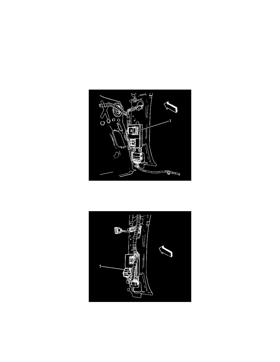
3. Disconnect the body wiring harness electrical connector (1) from the BCM.
4. Disconnect the I/P wiring harness electrical connector (1) from the BCM.