
i-290 2WD L4-2.9L (2008)
Knock Sensor: Service and Repair
Knock Sensor Replacement
Removal Procedure
1. Raise and support the vehicle only high enough to access the knock sensor (KS) through the wheelhouse. Refer to Lifting and Jacking the Vehicle
(See: Maintenance/Vehicle Lifting/Service and Repair) .
2. Remove the left wheelhouse liner. Refer to Front Wheelhouse Liner Replacement (See: Body and Frame/Fender/Front Fender/Front Fender
Liner/Service and Repair) .
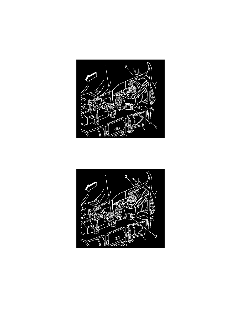
3. Disconnect the engine wiring harness electrical connector (3) from the KS (1).
4. Remove the KS retaining bolt.
5. Remove the KS (1) from the engine block.
Installation Procedure
Notice: Refer to Fastener Notice (See: Service Precautions/Vehicle Damage Warnings/Fastener Notice) .
1. Install the KS (1) and the retaining bolt to the engine block, positioning the electrical terminals rearward.
Tighten the knock sensor (KS) bolt to 25 N.m (18 lb ft).
2. Connect the engine wiring harness electrical connector (3) to the KS (1).
3. Install the left wheelhouse liner. Refer to Front Wheelhouse Liner Replacement (See: Body and Frame/Fender/Front Fender/Front Fender
Liner/Service and Repair) .
4. Lower the vehicle.