
i-290 2WD L4-2.9L (2008)
Important: Ensure that the dress cover and connector body are both in the released position before reassembling. Failure to do so may cause
damage to the connector and component.
Use the appropriate terminal and follow the instructions in the J-38125 .
Location of the terminal in the repair tray and the proper crimp tool can be found in the appropriate connector end view.
Bosch Connectors (0.64)
Bosch Connectors (0.64)
Tools Required
J-38125 Terminal Repair Kit
Terminal Removal Procedure
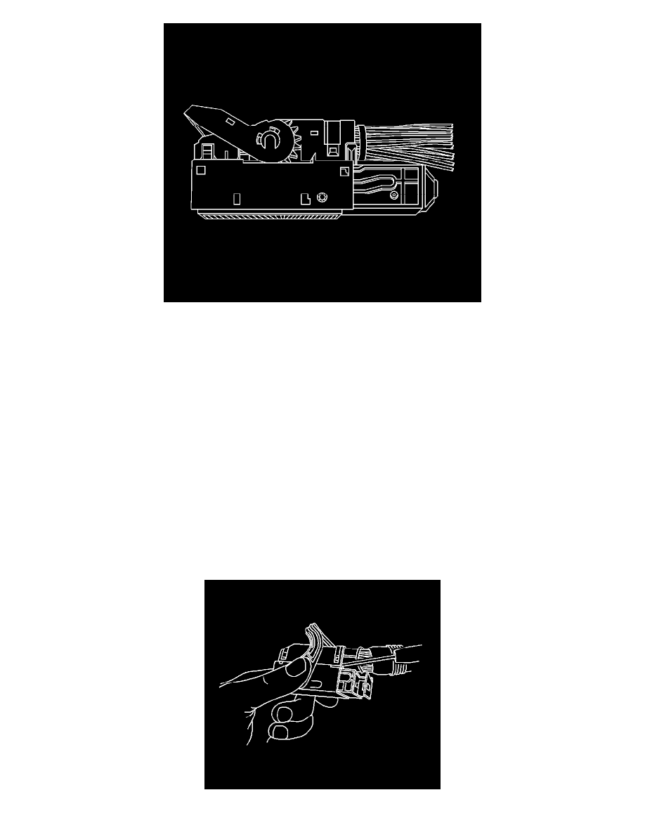
1. Locate the lever lock on the wire dress cover. While pressing the lock, pull the lever over and past the lock until the lever is at the end of its travel.
2. Disconnect the connector from the component.
3. Pull the rubber boot that covers the wires back to expose the end of the connector dress cover.
4. Place the connector locking lever in the center of the connector.