
i-290 2WD L4-2.9L (2008)
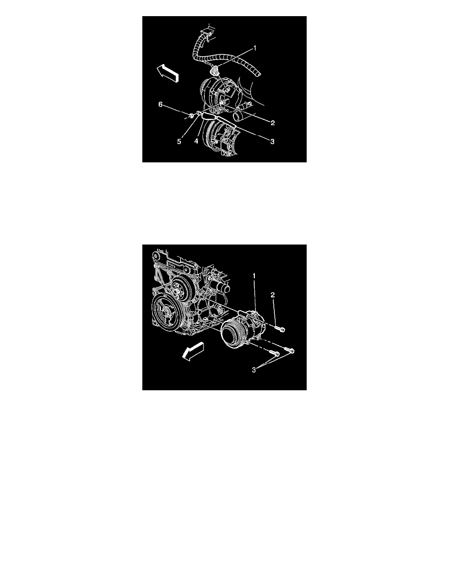
4. Connect the generator lead (5) to the generator and install the generator output BAT terminal nut (6).
Tighten the nut to 20 N.m (15 lb ft).
5. Press the protective boot (4) on to the generator output BAT terminal (2).
6. Connect the wiring harness connector (1) to the generator.
7. Raise and support the vehicle only high enough to access the A/C compressor through the wheelhouse. Refer to Lifting and Jacking the Vehicle (
See: Maintenance/Vehicle Lifting/Service and Repair) .
8. Position the A/C compressor (1) to the engine.
9. Install the A/C compressor mounting bolts (2, 3).
Tighten the bolts to 50 N.m (37 lb ft).
10. Attach the A/C compressor electrical connector to the bracket.
11. Install the left wheelhouse liner. Refer to Front Wheelhouse Liner Replacement (See: Body and Frame/Fender/Front Fender/Front Fender
Liner/Service and Repair) .
12. Install the left front wheel. Refer to Tire and Wheel Removal and Installation (See: Maintenance/Wheels and Tires/Service and Repair) .
13. Lower the vehicle.
14. Install the drive belt. Refer to Drive Belt Replacement (See: Engine, Cooling and Exhaust/Engine/Drive Belts, Mounts, Brackets and
Accessories/Drive Belt/Service and Repair) or Drive Belt Replacement (See: Engine, Cooling and Exhaust/Engine/Drive Belts, Mounts, Brackets
and Accessories/Drive Belt/Service and Repair) .
15. Connect the battery negative cable. Refer to Battery Negative Cable Disconnection and Connection (See: Battery/Battery Cable/Negative/Service
and Repair/Procedures) .