
i-290 4WD L4-2.9L (2007)
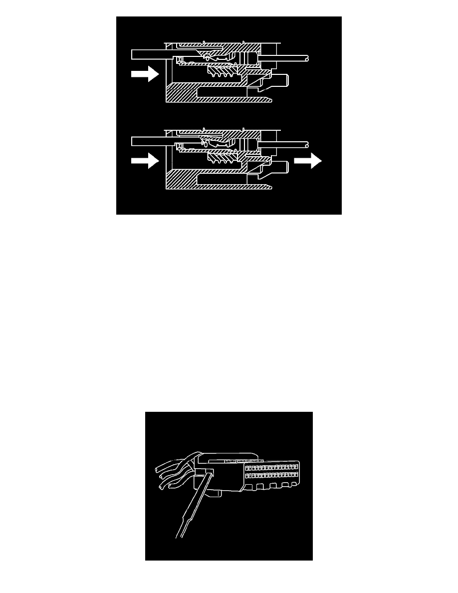
9. The illustration shows a cutaway view of the connector to aid the technician in releasing the terminal retainer.
10. See the release tool cross reference in the Reference Guide of the J-38125 Terminal Repair Kit to ensure that the correct release tool is used.
TERMINAL REPAIR PROCEDURE
Refer to the terminal crimping procedure in the Reference Guide of the J-38125 Terminal Repair Kit.
TERMINAL REPLACEMENT PROCEDURE
After the terminal is crimped to the wire, perform the following procedure in order to replace the terminal.
1. Slide the new terminal into the correct cavity at the back of the connector.
2. Push the terminal into the connector until it locks into place. The new terminal should be even with the other terminals. Insure that the terminal is
locked in place by gently pulling on the wire.
3. To assemble the connector, reverse the connector disassembly procedure.
Tyco/AMP Connectors (025 Cap)
TYCO/AMP CONNECTORS (025 CAP)
TOOLS REQUIRED
J-38125 Terminal Repair Kit
TERMINAL REMOVAL PROCEDURE
1. Disconnect the connector from the component by pressing down on the connector position assurance (CPA).