
i-350 L5-3.5L (2006)
Truck Bed: Technical Service Bulletins
Body - Pickup Box Reinforcements
Availability Of Pickup Box Reinforcements To Accommodate Aftermarket Accessory Tool Box Installation
ISSUE DATE: MARCH 2006
Affected Vehicles
2006 Isuzu i-280/i-350 (TI)
Service Information
Some customers may want to install an aftermarket hanging toolbox in the front of the pickup box.
This bulletin is to inform dealers that if a customer wants to have a hanging toolbox installed in the front of the pickup box, a reinforcement kit MUST be
installed prior to installation of the toolbox in order to avoid possible damage to the pickup box. Any load such as a toolbox or cap and the like on the
pickup bed rails will require this reinforcement kit.
A pickup box reinforcement kit, P/N 8-15833-028-0, has been released and is now available. This kit will contain the reinforcements and hardware
necessary for toolbox installation.
Use the following service procedure as a guide to install these reinforcements.
IMPORTANT:
The reinforcements must be installed before adding a toolbox. After the reinforcements have been installed, follow the instructions supplied with the
toolbox.
Pickup Box Front Reinforcement Installation
IMPORTANT:
The horizontal surfaces of the reinforcements must be flush to the horizontal surface of the pickup box top rail. Use a clamping tool when positioning
the reinforcements onto the top rail to ensure flushness to the outer panel.
1.
Place the front L-shaped reinforcements into position on the front top of the pickup box. For vehicles equipped with an over the rail bedliner or
bed rail protectors, these accessories should be removed with the aid of an assistant prior to installing these reinforcements.
2.
Using the reinforcement as a template, mark the holes necessary for drilling.
3.
Remove the front reinforcements.
IMPORTANT:
Use a block of wood and/or a drill stop for drill through protection in order to protect the back of the cab while drilling.
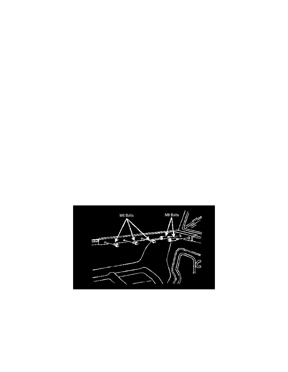
Drill two 13.5 mm (17/32) (0.54 in) holes per side into the box section of the front panel.
4.
Drill 7.5 mm (19/64) (0.30 in) holes into the weld flange of the side outer panel.
5.
Apply an approved anti-corrosion material to the drilled holes as necessary. Refer to the