
i-350 L5-3.5L (2006)
29. While guiding the forming mandrel into the exposed end of pipe to be flared, operate the lever of the J 45405 until the forming mandrel bottoms
against the clamping dies.
30. Rotate the hydraulic fluid control valve counterclockwise to the open position to allow the hydraulic forming ram to retract.
31. Insert the finishing cone into the forming ram.
32. Rotate the hydraulic fluid control valve clockwise to the closed position.
33. Rotate the body of the J 45405 until it bottoms against the die cage.
34. While guiding the finishing cone into the exposed end of pipe to be flared, operate the lever of the J 45405 until the finishing cone bottoms against
the dies.
35. Rotate the hydraulic fluid control valve counterclockwise to the open position to allow the hydraulic forming ram to retract.
36. Loosen the die clamping screw and remove the dies and pipe.
37. If necessary, lightly tap the dies until the die halves separate.
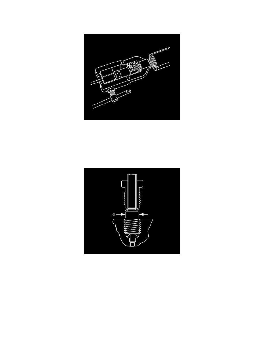
38. Inspect the brake pipe flare for correct shape and diameter (a).
^
6.92 mm (0.272 in) +/- 0.18 mm (0.007 in) flare diameter for 4.76 mm (3/16 in) diameter pipe
^
8.92 mm (0.351 in) +/- 0.18 mm (0.007 in) flare diameter for 6.35 mm (1/4 in) diameter pipe
39. If necessary, using the removed section of brake pipe as a template, shape the new pipe with a suitable brake pipe bending tool.
Important: When installing the pipe, maintain a clearance of 19 mm (3/4 in) from all moving or vibrating components.
Installation Procedure