
i-350 L5-3.5L (2006)
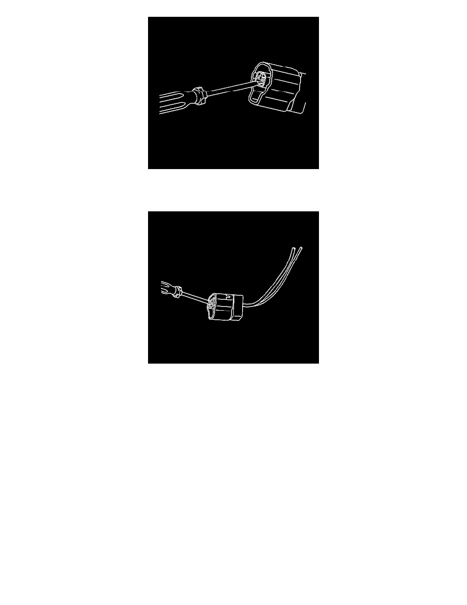
5. Insert the J 38125-553 (GM P/N 15315247) on a slight upward angle into the cavity below the terminal to be removed. Ensure that the pointed on
the end of the tool is facing the bottom of the terminal and it stays in contact with the terminal until it stops on the plastic terminal retainer. See the
release tool cross reference in the Reference Guide of the J 38125 to ensure that the correct release tool is used.
6. Gently pry the plastic terminal retainer down and carefully pull the terminal out of the connector. Always remember never use force when pulling a
terminal out of a connector. If the terminal is difficult to remove, repeat the entire procedure.
TERMINAL REPAIR PROCEDURE
Use the appropriate terminal and follow the instructions in the J 38125.
Repairing Connector Terminals
REPAIRING CONNECTOR TERMINALS
TOOLS REQUIRED
J 38125 Terminal Repair Kit
Use the following repair procedures in order to repair the following:
-
Push to Seat terminals
-
Pull to Seat terminals
Some terminals do not require all of the steps shown. Skip the steps that do not apply for your immediate terminal repair. The J 38125 contains further
information.
1. Cut off the terminal between the core and the insulation crimp. Minimize any wire loss.For cable seal terminals, remove the seal.
2. Apply the correct cable seal per gage size of the wire, if used.Slide the seal back along the wire in order to enable insulation removal.
3. Remove the insulation.
4. For sealed terminals only, align the seal with the end of the cable insulation.
5. Position the strip in the terminal.For sealed terminals, position the strip and seal in the terminal.