
i-350 L5-3.5L (2006)
1. Raise and support the vehicle. Refer to Vehicle Lifting.
2. Remove the tire and wheel assembly.
3. Support the lower control arm with a suitable jack stand.
4. Disconnect the front brake hose from the upper control arm. Refer to Brake Hose Replacement Front in Hydraulic brakes.
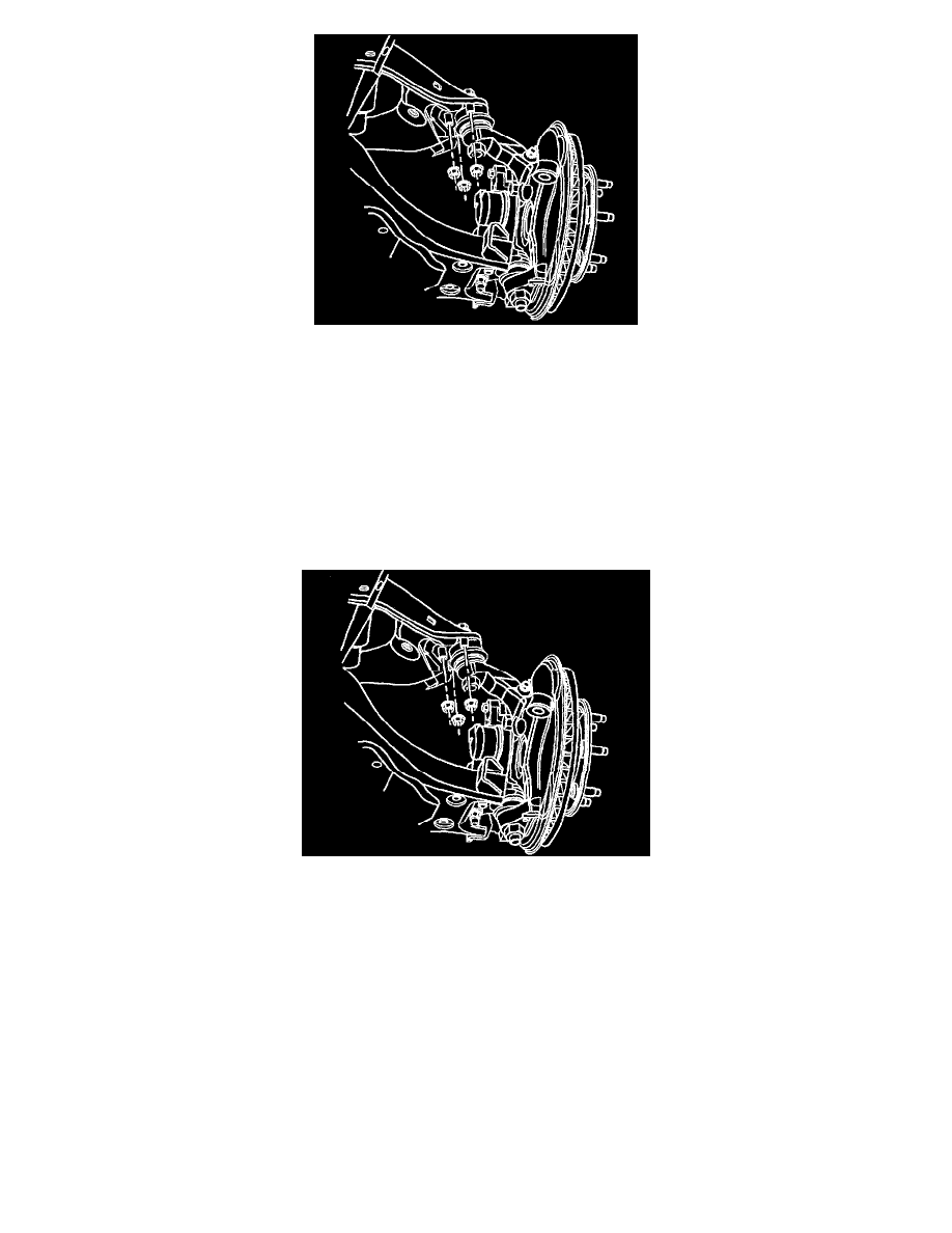
5. Remove the wheel speed sensor bracket bolt.
6. Disconnect the wheel speed sensor brackets.
7. Disconnect the upper control arm from the ball stud by removing the retention nuts. Discard the nuts.
8. Remove the nut from the upper ball joint. Discard the nut.
9. Disconnect the ball joint from the steering knuckle using the J 6627-A.
10. Remove the ball joint from the steering knuckle.
Installation Procedure
1. Install the ball joint to the steering knuckle.
Notice: Refer to Fastener Notice in Service Precautions.
2. Install the new nut to the upper ball joint.
^
Tighten the nuts to 75 Nm (55 ft. lbs.).
3. Connect the upper control arm to the ball stud by installing the retention nuts.
^
Tighten the nut to 47 Nm (35 ft. lbs.).
4. Connect the wheel speed sensor brackets.
5. Install the wheel speed sensor bracket bolt.
^
Tighten the nut to 20 Nm (15 ft. lbs.).
6. Connect the front brake hose to the upper control arm.
7. Install the tire and wheel assembly.
8. Remove the lower control arm support.
9. Lower the vehicle.
10. Verify the wheel alignment.