
i-350 L5-3.5L (2006)
2.
Obtain the supply fluid temperature from the machine display in "Idle" (The supply oil temperature must be greater than 18°C (65°F), or the
machine will not operate).
3.
Refer to the Quick Reference Card or Operator's Manual to determine the transmission oil cooler (T.O.C.) type and T.O.C. MINIMUM flow rate
specification.
4.
Record on the hard copy of the Repair Order, the T.O.C. MINIMUM flow rate and supply fluid temperature for future reference.
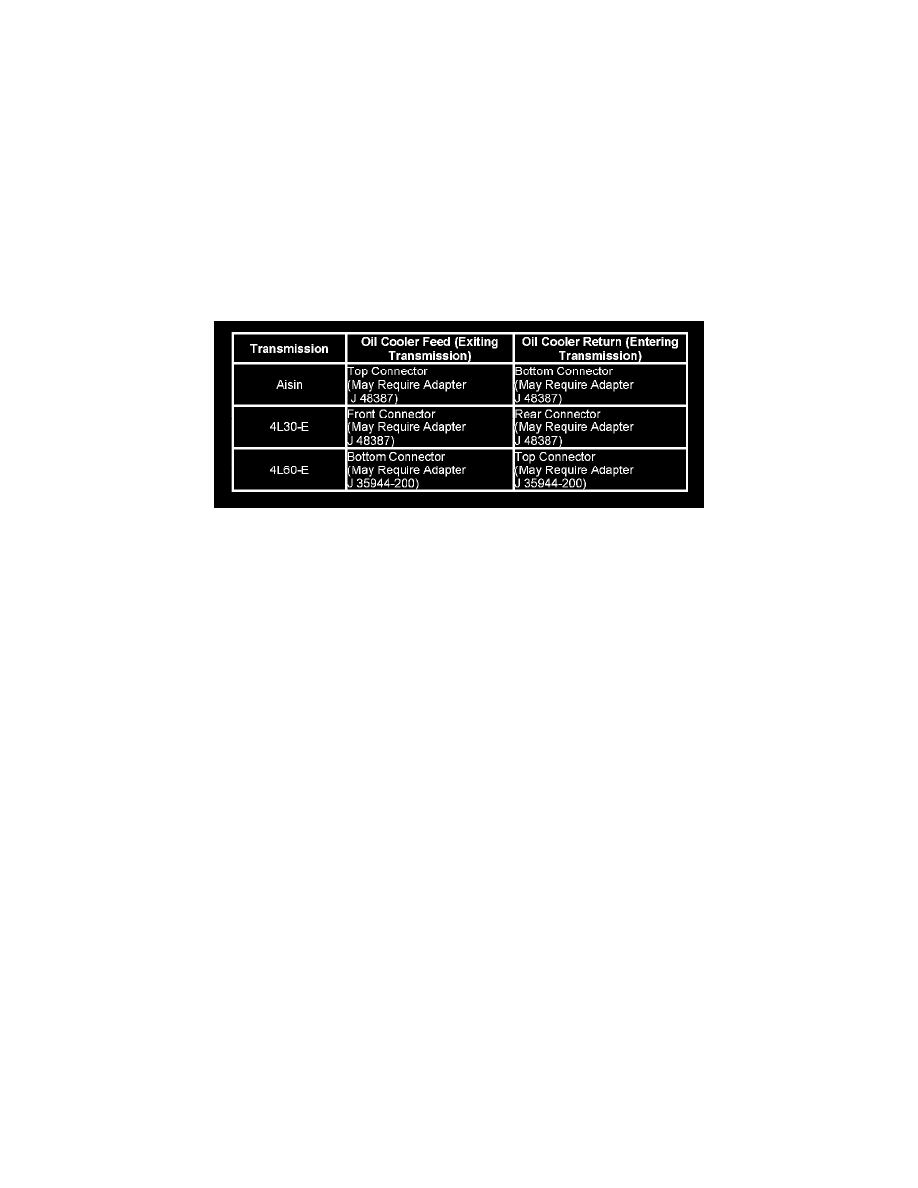
5.
Connect the supply (black) and waste (clear) hoses to the transmission oil cooler lines, at the transmission not the radiator, in the reverse flow
(back flush) direction. Refer to the table above for T.O.C. flow direction. Use appropriate adapters as required.
6.
Turn the Function Switch to "Flush". Allow the machine to operate for 30 seconds. (Dirty oil may be seen as it is flushed out through the clear
hose.)
7.
Turn the Function Switch to "Idle".
8.
Reverse the supply and waste hoses on the cooler lines to the normal flow direction. Refer to the above table.
9.
Turn the Function Switch to "Flush" and allow the machine to operate for 30 seconds. Again, dirty oil may be visible in the clear hose.
10.
Turn the Function Switch to "Flow" and allow the oil to flow for 15 seconds. Observe and record the tested flow rate on the hard copy of the repair
order.
11.
Refer to the MINIMUM flow rate and temperature information you recorded in Step 4.
12.
Compare the tested flow rate to the MINIMUM flow rate specification.
^
If the tested flow rate is equal to or GREATER than the MINIMUM flow rate, go to Step 14.
^
If the tested flow rate is LESS than the MINIMUM flow rate, repeat Steps 5 through 12. If the tested flow rate is LESS than the MINIMUM
flow rate after the second test, go to Step 13.
13.
Turn the Function Switch to "Code." Record the tested flow rate, temperature, cycle and flow code information on the repair order.
A.
Replace the T.O.C. after replacing the T.O.C., continue with the next step to validate the flow rate of the new T.O.C.
B.
Reconnect the supply and waste hoses to the cooler lines in the normal flow direction. Go back to Step 10.
14.
Turn the Function Switch to "Code." Record the tested flow rate, temperature, cycle and flow code information on the repair order.
15.
Turn the Function Switch to "Idle" and allow the supply vessel pressure to dissipate.
16.
Turn the main power switch to OFF.
NOTE:
Flow rates are only applicable to the Kent Moore J 45096 transmission oil cooling system flush and flow test tool.
Modifying J 35944-200 Adapter
A new longer pilot 9.525 mm (0.375 in) automatic transmission oil cooler line went into production on some 2005 model year vehicles.
The new cooler line will not fit into the existing J 35944-200 adapter that is used with J 45096 Transmission Oil Cooler Flush and Flow Test tool. In the