
i-350 L5-3.5L (2006)
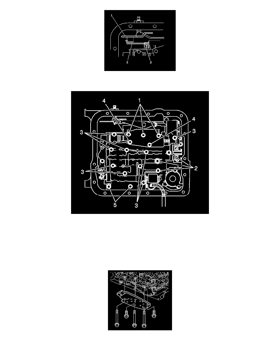
3. Verify that the manual valve link (3) is installed properly to the inside detent lever (1) and the manual valve (2).
4. Install one bolt (M6 X 1.0 X 47.5) hand tight in the center of the valve body to hold it in place.
5. Important: When installing bolts throughout this procedure, be sure to use the correct bolt size and length in the correct location as specified.
Do not install the transmission fluid indicator stop bracket and bolt at this time, if equipped Install but do not tighten the control valve body bolts
securing only the valve body directly. Each numbered bolt location corresponds to a specific bolt size and length, as indicated by the following:
^
M6 X 1.0 X 65.0 (1)
^
M6 X 1.0 X 54.4 (2)
^
M6 X 1.0 X 47.5 (3)
^
M6 X 1.0 X 17.7 (4)
^
M6 X 1.0 X 35.0 (5)
6. Install the TFP manual valve position switch.
7. Install but do not tighten the control valve body bolts securing the TFP manual valve position switch to the control valve body.