
i-370 4WD L5-3.7L (2007)
3. Ensure that the terminal release tang access panel is in the correct location to access the terminals.
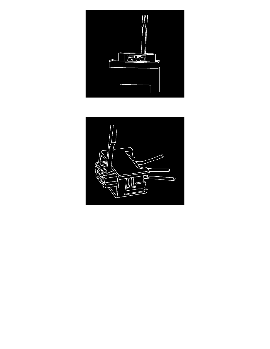
4. Push the wire side of the terminal that is being removed toward the connector and hold it in position.
5. Insert the J 38125-11A (GM P/N 12094430) into the terminal release tang access slot located behind the access panel of the connector and press
down on the terminal while carefully pulling the terminal out of the connector. Always remember never use force when pulling a terminal out of a
connector. If the terminal is difficult to remove, repeat the entire procedure.
TERMINAL REPAIR PROCEDURE
Use the appropriate terminal and follow the instructions in the J-38125.
Tyco/AMP Connectors (43-Way)
TYCO/AMP CONNECTORS (43-WAY)
TOOLS REQUIRED
J-38125 Terminal Repair Kit
REMOVAL PROCEDURE
Follow the steps below in order to remove terminals from the connector.
1. Locate the lever lock on the wire dress cover. Slide the lever lock away from the connector body.
2. Disconnect the connector from the component.
3. Locate the dress cover locking tabs on the dress cover of the connector. Using a small flat-blade tool release all of the locking tabs.
4. Once the locks are unlocked, lift the dress cover off.
5. IMPORTANT: Always use care when removing a terminal position assurance (TPA) in order to avoid damaging it.