
NPR L4-5.2L DSL Turbo (2005)
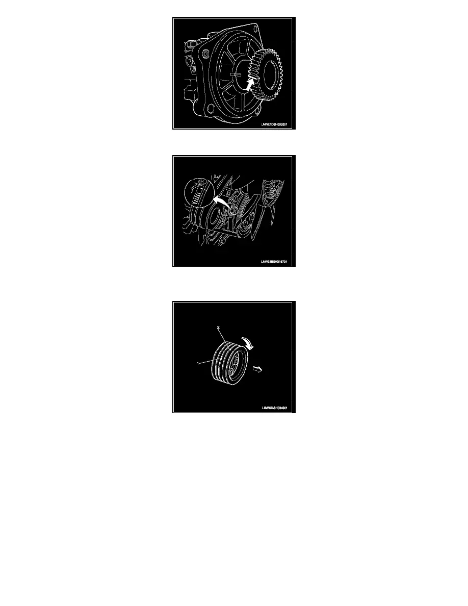
4. Apply white paint to the top of the fuel supply pump gear tooth directly above the stamped 'O' mark. Refer to the illustration.
5. Turn the crankshaft in the normal direction of engine rotation until the No. 1 or No. 4 cylinder is at TDC on the compression stroke. Refer to the
illustration.
NOTE:
-
There are 2 timing marks on the crankshaft pulley.
-
Mark (1) is near the front cover and is used to bring the 4HK1-TC engine to TDC.
-
Mark (2) is not applicable to this engine.
-
Be sure to use mark (1) when bringing the engine to TDC.
6. Remove the oil drain adapter.
7. Install the O-ring to the fuel supply pump.
8. Align the slits as shown in the illustration.
9. Insert the stud bolts into the guides and temporarily tighten them.
CAUTION:
-
If the stud bolts (cylinder block side) have been loosened or replaced, apply Loctite 262 to the recessed portion of the bolts.