
Oasis LS L4-2156cc 2.2L SOHC MFI F22B6 (1997)
Maintenance Bleeder
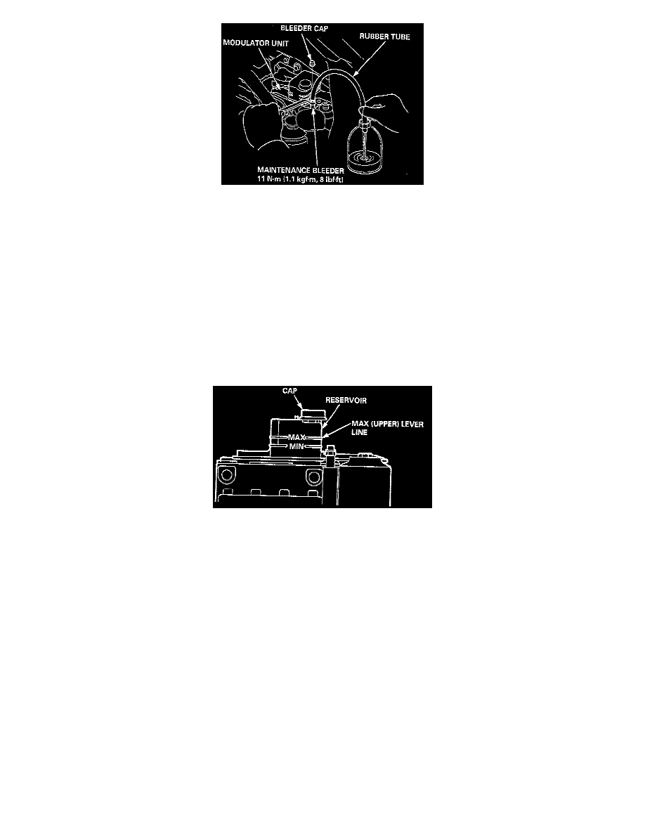
A) Attach a wrench to the maintenance bleeder.
B) Connect a rubber tube of the appropriate diameter to the maintenance bleeder, and set the other end of the rubber tube in a suitable container.
C) While holding the rubber tube with your hand, slowly loosen the maintenance bleeder 1/8 to 1/4 turn to collect the brake fluid in the container.
CAUTION: Do not loosen the maintenance bleeder too much. The high-pressure brake fluid can burst out.
D) Start the engine and let it idle for a minute. Stop the engine.
E) Check the brake fluid level in the reservoir. It should be below the MAX (upper) level line.
F) Tighten the maintenance bleeder.
Brake Fluid Reservoir
4. Remove the cap, and refill the reservoir to the MAX (upper) level with fresh brake fluid.
NOTE: Pour the brake fluid slowly so that it does not foam, and wait for a few minutes.
5. Repeat steps A through F twice, and refill the reservoir to the MAX (upper) level with fresh brake fluid.
6. Tighten the maintenance bleeder to the specified torque.
7. After replacement, start the engine and make sure that the ABS indicator light goes off.
Specs:
Maintenance Bleeder 11 Nm (8 lb. ft.)
Fluid Capacity (approx) 150 ml (5.0 fl-oz)
System Bleed
NOTE: The ABS can also be bled by using the Honda PGM Tester and the ABS Diagnostic Kit to run the ABS pump. Connect the tester and module A
(refer to PGM users guide), then follow the tester's prompts instead of this procedure.
CAUTION: When the brake fluid is completely drained from the reservoir (air enters in the modulator unit) during brake fluid replacement, bleed the
air from the modulator unit as follows.
1. Fill the reservoir to the MAX (upper) level with fresh brake fluid.