
Oasis LS L4-2156cc 2.2L SOHC MFI F22B6 (1997)
OK.
All connectors are numbered (C709, C416, etc.). Below each connector number (except those for components) is the number of a photo showing the
connector's location on the car. Connector cavities are also numbered. The numbering sequence begins at the top left corner of the connector as seen
from either of the viewpoints shown. Disregard any numbers molded into the connector housing.
Wires are identified by the abbreviated names of their colors; the second color is the color of the stripe. Wires are also identified by their location in a
connector. The number "2" next to the male and female wire terminals at C416, for example, means those terminals join in cavity 2 of connector C416.
Power Distribution Schematics
Power Distribution schematics show how power is supplied from the positive battery terminal to various circuits in the car. Refer to the power
distribution section to get a more detailed picture of how power is supplied to the circuit you're working on.
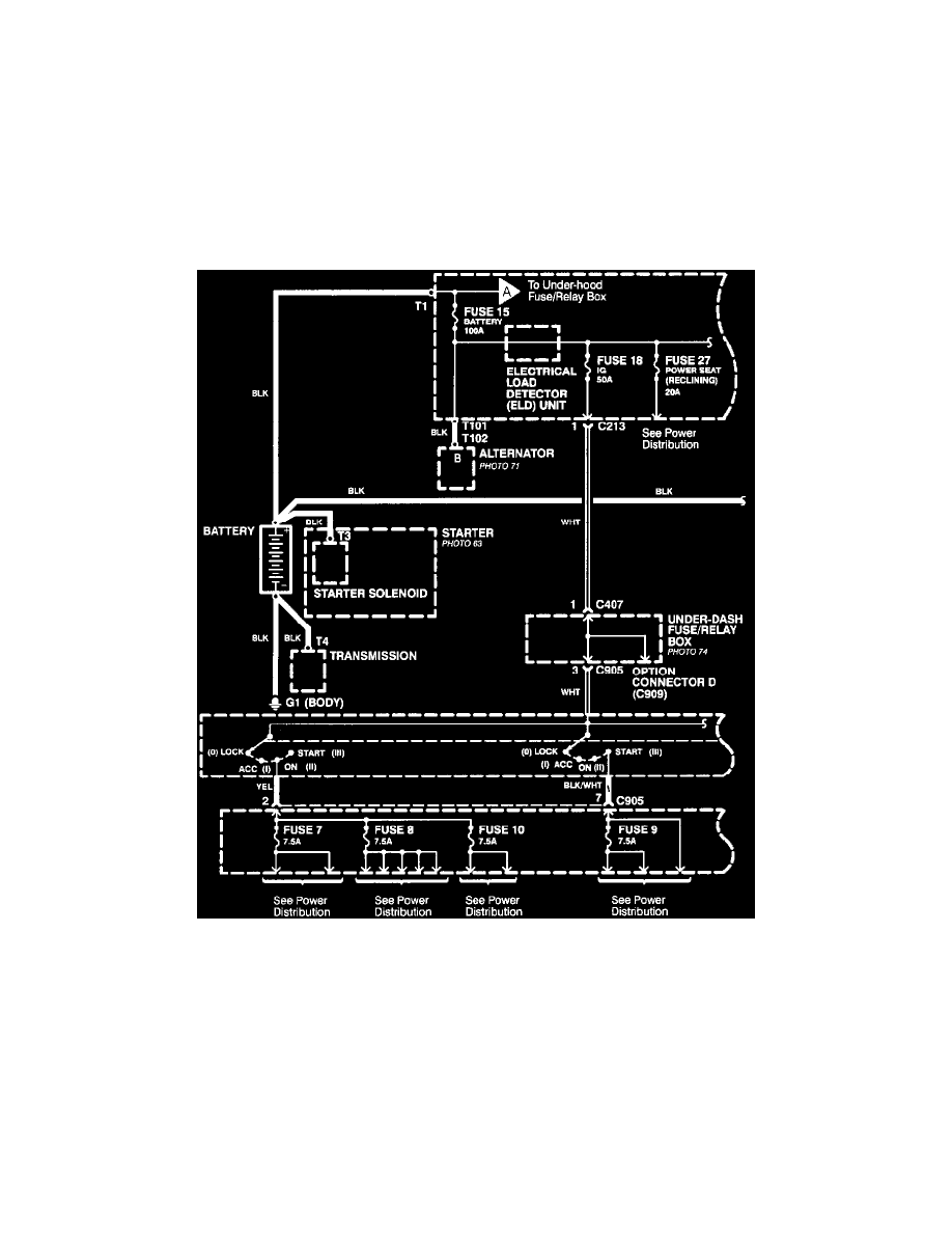
Power Distribution Schematics ( From Battery To Ignition Switch, Fuses And Relays
From Battery to Ignition Switch, Fuses, and Relays
Individual circuit schematics begin with a fuse. The first half of power distribution, however, shows the wiring "upstream" between the battery and
the fuses.