
Oasis S L4-2253cc 2.3L SOHC VTEC MFI (1998)
Each schematic represents one circuit. A circuit's wires and components are arranged to show current flow, from power at the top of the image, to
ground, at the bottom.
Other circuits may share power or ground terminals or wiring with the circuit shown. A wire that connects one circuit to another, for example, is cut short
and has an arrowhead at the end of it pointing in the direction of current flow. Next to the arrowhead is the name of the circuit or component which
shares that wiring. To quickly check shared wiring, check the operation of a component it serves. If that component works, you know the shared wiring is
OK.
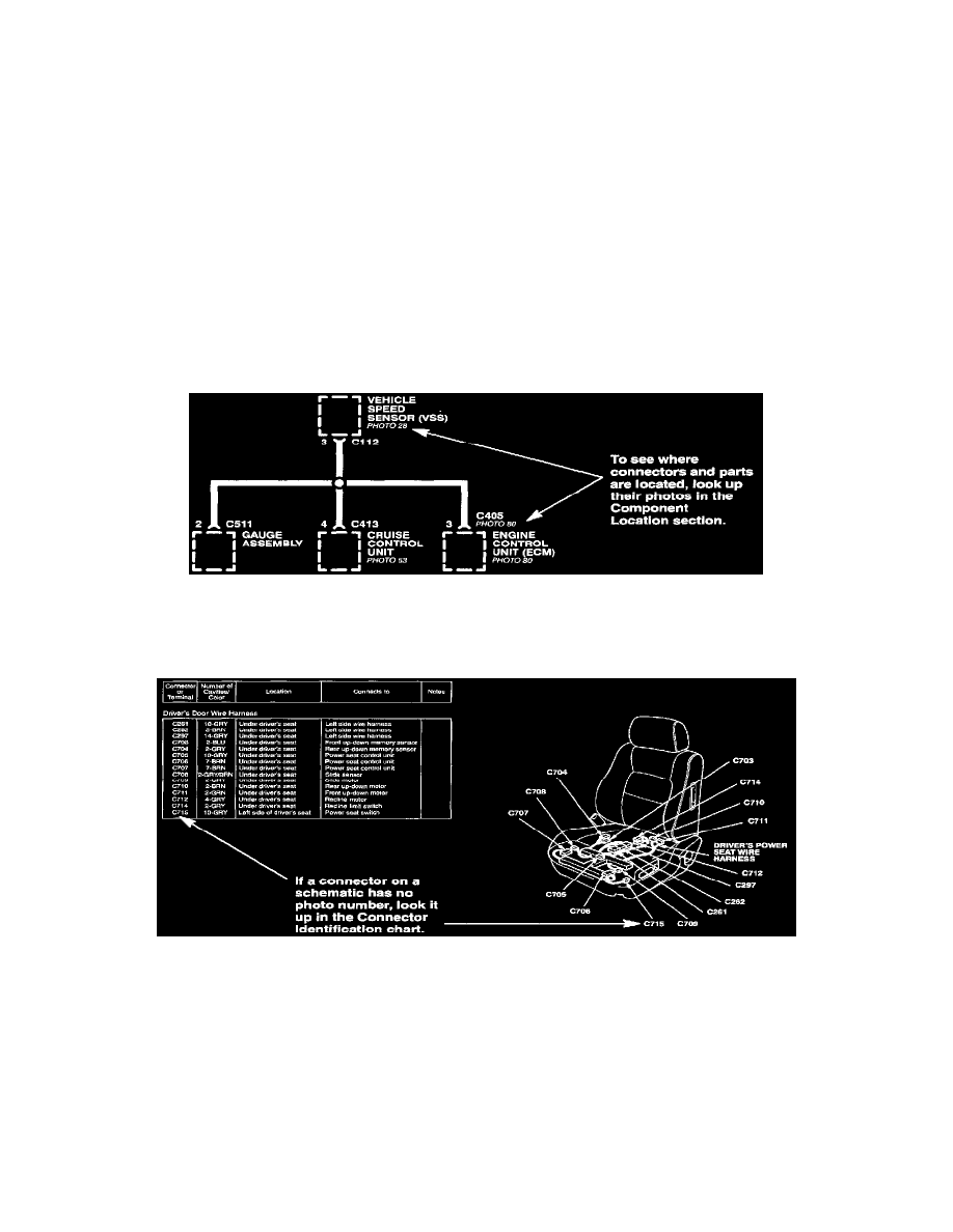
All connectors are numbered (C709, C416, etc.). Below each connector number (except those for components) is the number of a photo in the back of
the book showing the connector's location on the car. Connector cavities are also numbered. The numbering sequence begins at the top left corner of the
connector as seen from either of the viewpoints. Disregard any numbers molded into the connector housing.
Wires are identified by the abbreviated names of their colors; the second color is the color of the stripe. Wires are also identified by their location in a
connector. The number "2" next to the male and female wire terminals at C416, for example, means those terminals join in cavity 2 of connector C416.
A complete description of schematic symbols is given under wire color abbreviations.
Component Locations
Component Locations
To see where a component or connector is located on the car, look up its photo number in the component location section. The photo will also tell you
the color of the connector and how many cavities it has.
Component Locations
If there is no photo number below or beside a component name or a connector, ground, or terminal number, look up that name or number in the
appropriate Connector Identification Chart. The chart lists how many cavities a connector has, where it's located, and what it connects to. The related
illustration shows the connector's location on the harness, and the harness routing.
Ground Distribution Schematics