
Oasis S L4-2253cc 2.3L SOHC VTEC MFI (1998)
General Module: Testing and Inspection
SRS components are located in this area. Review the SRS component locations, precautions, and procedures in the SRS section before performing
repairs or service.
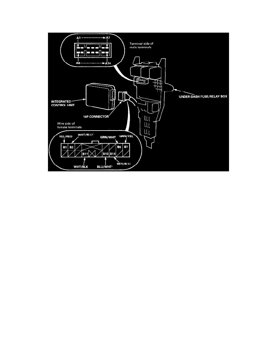
1. Remove the driver's side kick panel, then disconnect the 16-P connector from the integrated control unit.
2. Remove the integrated control unit from the under- dash fuse/relay box.
3. Inspect the connector and socket terminals to be sure they are all making good contact.
^
If the terminals are bent, loose or corroded, repair them as necessary, and recheck the system.
^
If the terminals look OK, make the following input tests at the connectors.
-
If any test indicates a problem, find and correct the cause, then recheck the system.
-
If all the input tests prove OK, the control unit must be faulty; replace it.