
Oasis S L4-2253cc 2.3L SOHC VTEC MFI (1998)
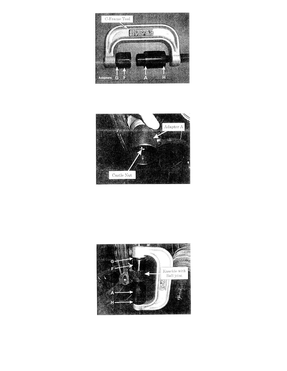
Figure 6: Arrange adapters to C-Frame Tool.
11.
Arrange the special tools for ball joint removal. (Figure 6)
Figure 7: Install adapter (A) to ball joint using castle nut.
12.
Install Remover/Installer Adapter (A) to the ball joint with the castle nut. (Figure 7)
13.
Clean the recessed area around the ball joint cap and knuckle with solvent and compressed air. To remove remaining debris, a brush may be used.
This is necessary to allow proper seating of base remover adapter (F) around the ball joint cap.
IMPORTANT
Incorrect seating (misalignment) of adapter (F) due to foreign debris will result in possible damage to tool during Step 15.
Figure 8: Position the adapters for ball joint removal.
14.
Position the special tool onto the lower ball joint and knuckle. (Figure 8)
^
To avoid damaging the special tools, verify that the correct tools are used and aligned properly.
15.
Using the C-frame with proper adapters (G, F, A, and H), press the lower ball joint out of the knuckle by tightening the C-frame.