
Rodeo 2WD V6-3.2L (2003)
Engine Control Module: Description and Operation
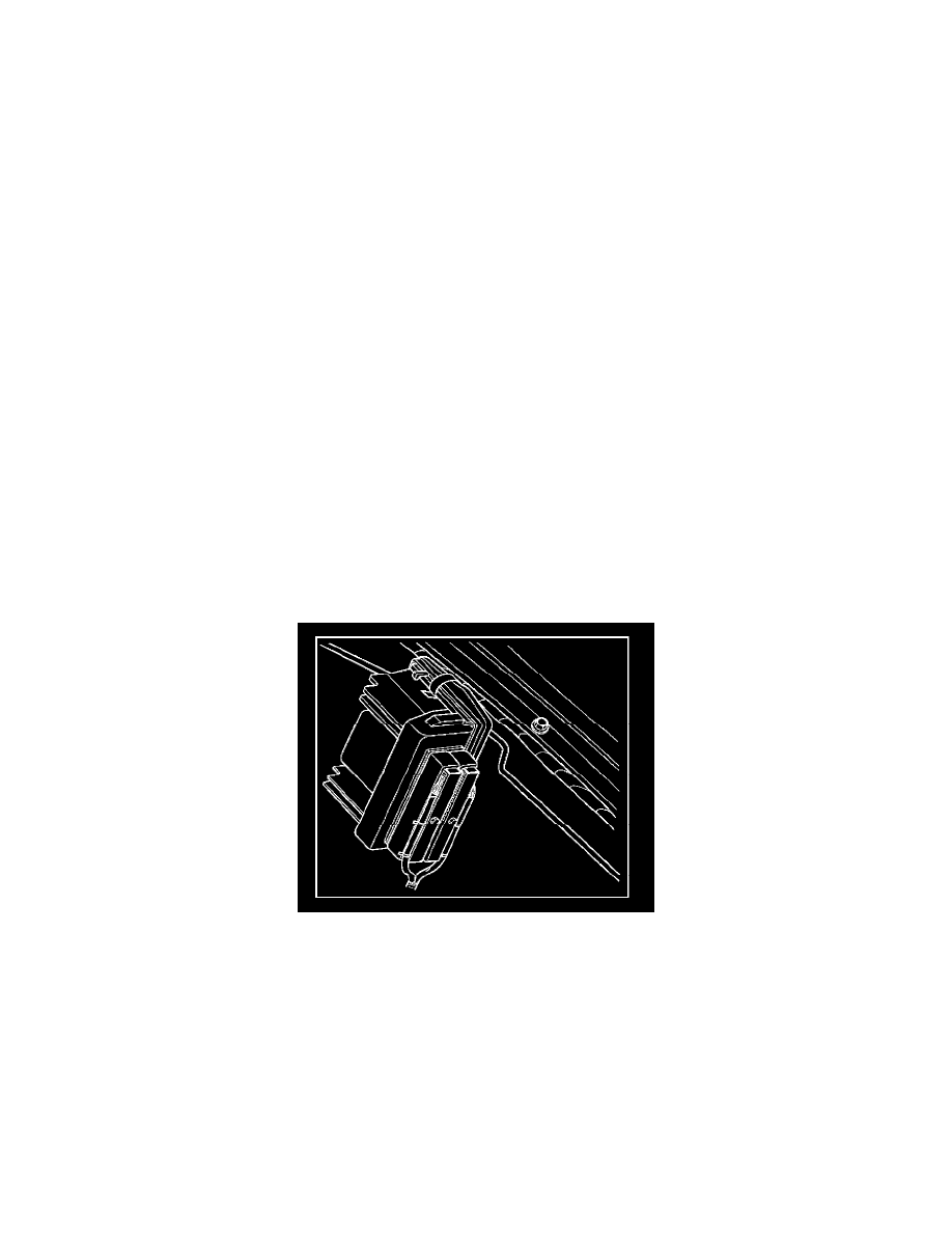
Powertrain Control Module (PCM)
The powertrain control module (PCM) is located on the driver side fender in the engine compartment. The PCM controls the following:
-
Fuel metering system.
-
Transmission shifting (automatic transmission only).
-
Ignition timing.
-
On-board diagnostics for powertrain functions.
The PCM constantly observes the information from various sensors. The PCM controls the systems that affect vehicle performance. The PCM performs
the diagnostic function of the system. It can recognize operational problems, alert the driver through the MIL (Check Engine lamp), and store diagnostic
trouble codes (DTCs). DTCs identify the problem areas to aid the technician in making repairs.
EEPROM
The electrically erasable programmable read only memory (EEPROM) is a permanent memory chip that is physically soldered within the PCM. The
EEPROM contains the program and the calibration information that the PCM needs to control powertrain operation.
Unlike the PROM used in past applications, the EEPROM is not replaceable. If the PCM is replaced, the new PCM will need to be programmed.
Equipment containing the correct program and calibration for the vehicle is required to program the PCM.
PCM Components
The PCM is designed to maintain exhaust emission levels to government mandated standards while providing excellent driveability and fuel efficiency.
The PCM monitors numerous engine and vehicle functions via electronic sensors such as the throttle position (TP) sensor, heated oxygen sensor (HO2S),
and vehicle speed sensor (VSS). The PCM also controls certain engine operations through the following:
-
Fuel injector control
-
Ignition control module
-
ION sensing module
-
Automatic transmission shift functions
-
Cruise control
-
Evaporative emission (EVAP) purge
-
A/C clutch control
PCM Function
The PCM supplies either 5 or 12 volts to power various sensors or switches. The power is supplied through resistances in the PCM which are so high in
value that a test light will not light when connected to the circuit. In some cases, even an ordinary shop voltmeter will not give an accurate reading
because its resistance is too low. Therefore, a digital voltmeter with at least 10 megohms input impedance is required to ensure accurate voltage
readings. Tool J 39200 meets this requirement. The PCM controls output circuits such as the injectors, fan relays, etc., by controlling the ground or the
power feed circuit through transistors or through either of the following two devices:
-
Output Driver Module (ODM)
-
Quad Driver Module (QDM)
PCM Voltage Description
The PCM supplies a buffered voltage to various switches and sensors. It can do this because resistance in the PCM is so high in value that a test light
may not illuminate when connected to the circuit. An ordinary shop voltmeter may not give an accurate reading because the voltmeter input impedance is
too low. Use a 10-megohm input impedance digital voltmeter (such as J 39200) to assure accurate voltage readings.
The input/output devices in the PCM include analog-to-digital converters, signal buffers, counters, and special drivers. The PCM controls most
components with electronic switches which complete a ground circuit when turned "ON." These switches are arranged in groups of 4 and 7, called either