
Rodeo 2WD V6-3.2L (2003)
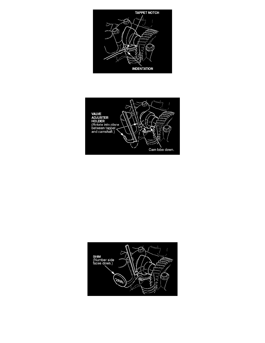
7. Turn the valve tappet with a pick or a small screwdriver until the tappet notch is within the indentation in the head.
8. Turn the crankshaft (or camshaft) pulley clockwise until the cam lobe presses the valve fully open.
9. On the tappet side closest to the bearing cap, insert the valve adjuster holder (T/N J-42659-AH) between the camshaft and the tappet. The tool
should rest on the edge of the tappet without touching the shim.
10. Slowly turn the crankshaft (or camshaft) pulley counterclockwise so that when the valve closes, the tool catches between the camshaft and the
tappet, holding the valve slightly open.
NOTE:
Do not turn the crankshaft (or camshaft) pulley too far or in the wrong direction. If you do, you might break the tool, or worse yet, damage the
cylinder head.
11. Insert a pick or a small screwdriver into the tappet notch, and pry out the shim.
12. Wipe off the shim, then write its number on the Valve Inspection Chart for that valve and cylinder. If there is no number on the shim, measure its
thickness with a micrometer, and write down the measurement on the Valve Inspection Chart.
13. Follow the directions on the Valve Shim Replacement Chart to select the correct shim.
14. Insert the correct shim, number side down, into the tappet. Make sure the shim is fully seated.
15. Release and remove the tool by turning the crankshaft (or camshaft) pulley clockwise.
16. Turn the crankshaft (or camshaft) pulley clockwise until the cam lobe again points away from the valve.