
Rodeo LSE 4WD V6-3.2L (2000)
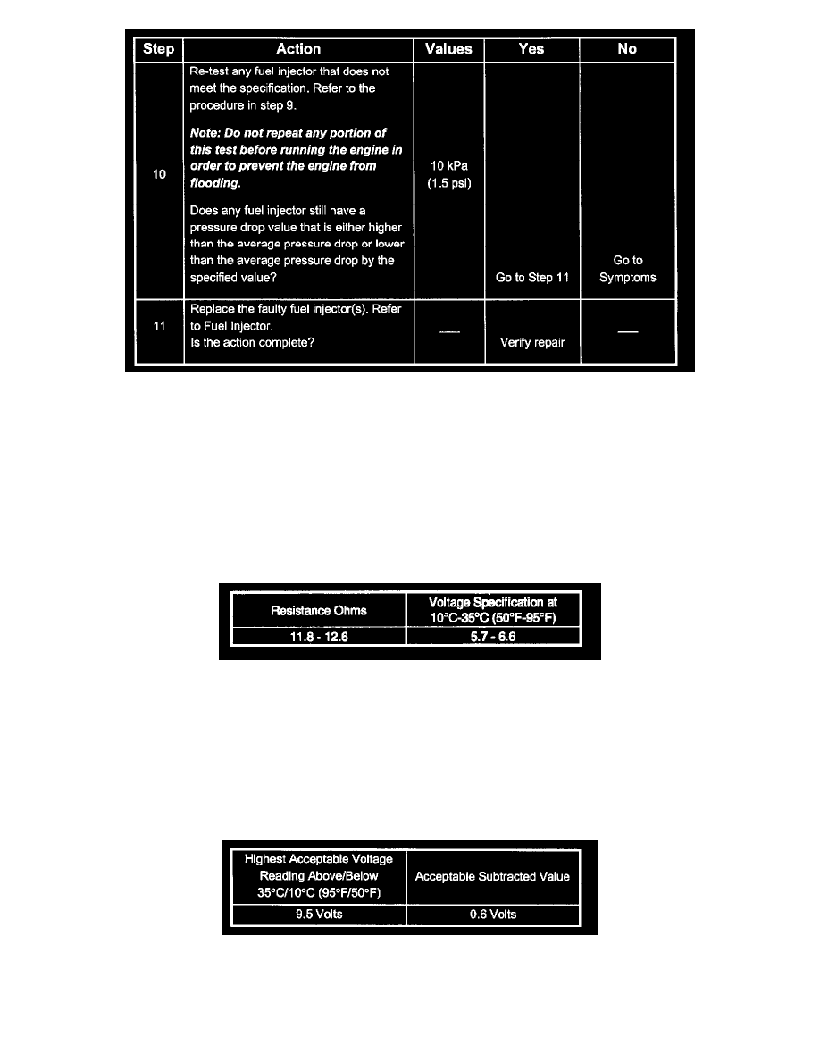
Steps 10 - 11
Test Description
Number(s) below refer to the step number(s) on the Diagnostic Chart:
2. Relieve the fuel pressure by connecting the J 34730-1 Fuel Pressure Gauge to the fuel pressure connection on the fuel rail.
CAUTION: In order to reduce the risk of fire and personal injury, wrap a shop towel around the fuel pressure connection. The towel will absorb
any fuel leakage that occurs during the connection of the fuel pressure gauge. Place the towel in an approved container when the connection of the
fuel pressure gauge is complete.
Place the fuel pressure gauge bleed hose in an approved gasoline container.
With the ignition switch "OFF," open the valve on the fuel pressure gauge.
Injector Specifications
3. Record the lowest voltage displayed by the DVM after the first second of the test. (During the first second, voltage displayed by the DVM may be
inaccurate due to the initial current surge.)
Injector Specifications:
-
The voltage displayed by the DVM should be within the specified range.
-
The voltage displayed by the DVM may increase throughout the test as the fuel injector windings warm and the resistance of the fuel injector
windings changes.
-
An erratic voltage reading (large fluctuations in voltage that do not stabilize) indicates an intermittent connection within the fuel injector.
5. Injector Specifications:
7. The Fuel Injector Balance Test portion of this chart (Step 7 through Step 11) checks the mechanical (fuel delivery) portion of the fuel injector. An
engine cool-down period of 10 minutes is necessary in order to avoid irregular fuel pressure readings due to Hot Soak" fuel boiling.