
Rodeo S 4WD V6-3.2L (1999)
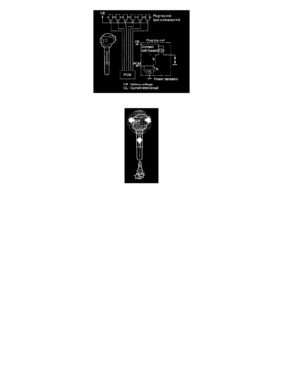
Based on these sensor signals and engine load information, the PCM sends 5V to each ignition coil.
The PCM applies 5V signal voltage to the ignition coil requiring ignition. This signal sets on the power transistor of the ignition coil to establish a
grounding circuit for the primary coil, applying battery voltage to the primary coil. At the ignition timing, the PCM stops sending the 5V signal voltage.
Under this condition the power transistor of the ignition coil is set oft to cut the battery voltage to the primary coil, thereby causing a magnetic field
generated in the primary coil to collapse. On this moment a line of magnetic force flows to the secondary coil, and when this magnetic line crosses the
coil, high voltage induced by the secondary ignition circuit to flow through the spark plug to the ground.