
Rodeo Sport 2WD V6-3.2L (2001)
4. Install snap ring.
5. Install Combination switch and SRS coil assembly. After installation of combination switch assembly, connect the combination switch wiring
harness connector and the SRS 2-way connector located under the steering column.
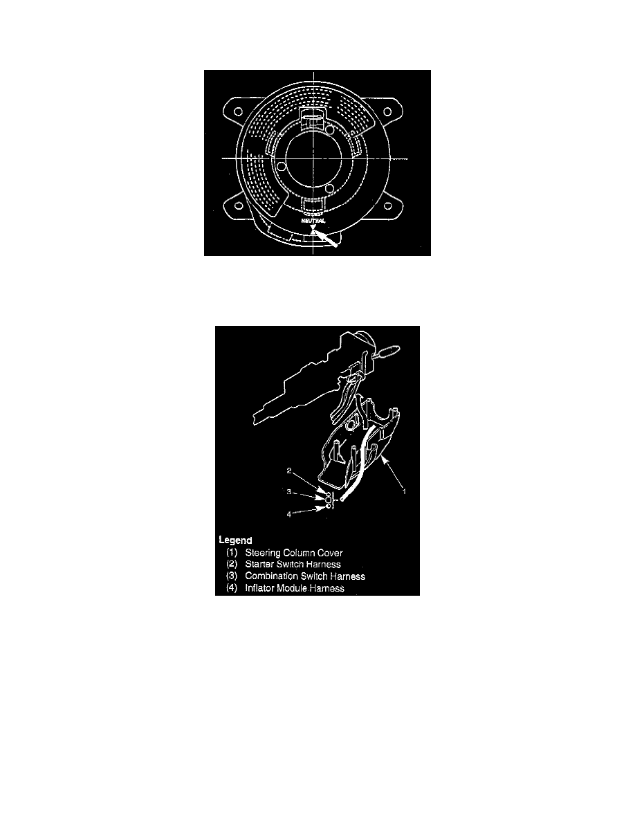
6. Turn the SRS coil counter clockwise to full, return about 3 turns and align the neutral mark.
Caution: When turning the SRS coil counter clockwise to full, stop turning if resistance is felt. Forced further turning may damage the cable in
the SRS coil.
7. When installing the steering column cover, be sure to wire (through each harness) as illustrated so that the harnesses starter switch, combination
switch and SRS coil may not catch wiring.
8. Install steering wheel by aligning the setting marks made during removal.
Caution: Never apply force to the steering wheel in direction of the shaft by using a hammer or other impact tools in an attempt to remove the
steering wheel. The steering shaft is designed as an energy absorbing unit.
9. Tighten the steering wheel fixing nut to the specified torque.
Torque: 34 Nm (25 ft. lbs.)
10. Support inflator module and carefully connect the SRS connector and horn lead, then install inflator module.
Note: Pass the lead wire through the tabs on the plastic cover (wire protector) of inflator to prevent lead wire from being pinched.
11. Tighten fixing bolts to specified torque.
Torque: 9 Nm (78 inch lbs.)
12. Install driver knee bolster (reinforcement).