
Rodeo Sport 2WD V6-3.2L (2001)
3. Remove upper ball joint nut and cotter pin, then use remover J-36831 to remove the upper ball joint from the knuckle.
Caution: Be careful not to damage the ball joint boot.
4. Remove bolt and nut.
5. Remove upper ball joint.
Inspection and Repair
Make necessary parts replacement if wear, damage, corrosion or any other abnormal conditions are found through inspection.
-
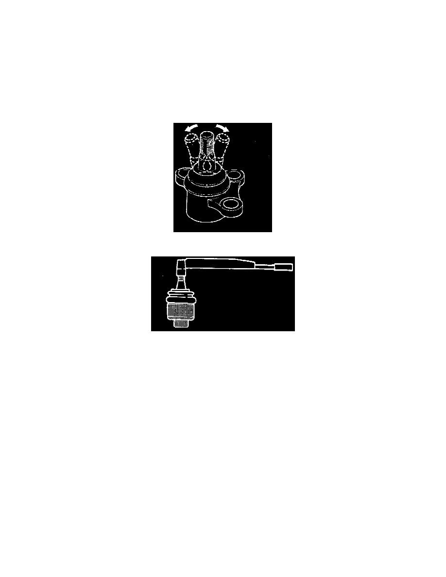
Inspect the lower end boot for damage or grease leak. Move the ball joint as shown in the figure to confirm its normal movement.
-
Inspect screw/taper area of ball for damage.
-
If any defects are found by the above inspections, replace the ball joint assembly with new one.
-
After moving the ball joint 4 or 5 times, attach nut then measure the preload.
Starting torque: 0.5 - 3.2 Nm (0.4 - 2.4 ft. lbs.)
-
If the above limits specified are exceeded, replace the ball joint assembly.
Installation
1. Install upper ball joint.
2. Install bolt and nut, then tighten them to the specified torque.
Torque: 57 Nm (42 ft. lbs.)
3. Install nut and cotter pin, then tighten the nut to the specified torque with just enough additional torque to align cotter pin holes.
Install new cotter pin.
Torque: 98 Nm (72 ft. lbs.)