
Trooper LS 2WD V6-3.5L (2001)
Seat Belt Reminder Lamp: Diagnostic Aids
Voltmeter and Test Light
Use a voltmeter or test light to check for voltage. While a test light shows whether or not voltage is present, a voltmeter indicates how much voltage there
is.
CAUTION: A number of circuits include solid state devices. Voltages in these circuits should be tested only with a 10-megohms or higher impedance
digital multimeter. Never use a test light on circuits that contain solid-state devices. Damage to the device may result.
On circuits without solid-state devices, a test light may be used to check for voltage. A test light is made up of a 12-volts bulb with a pair of leads
attached. After grounding one lead, touch the other lead to various points along the circuit where voltage should be present. The bulb will go on if the
voltage at the point being tested is greater than 5 volts.
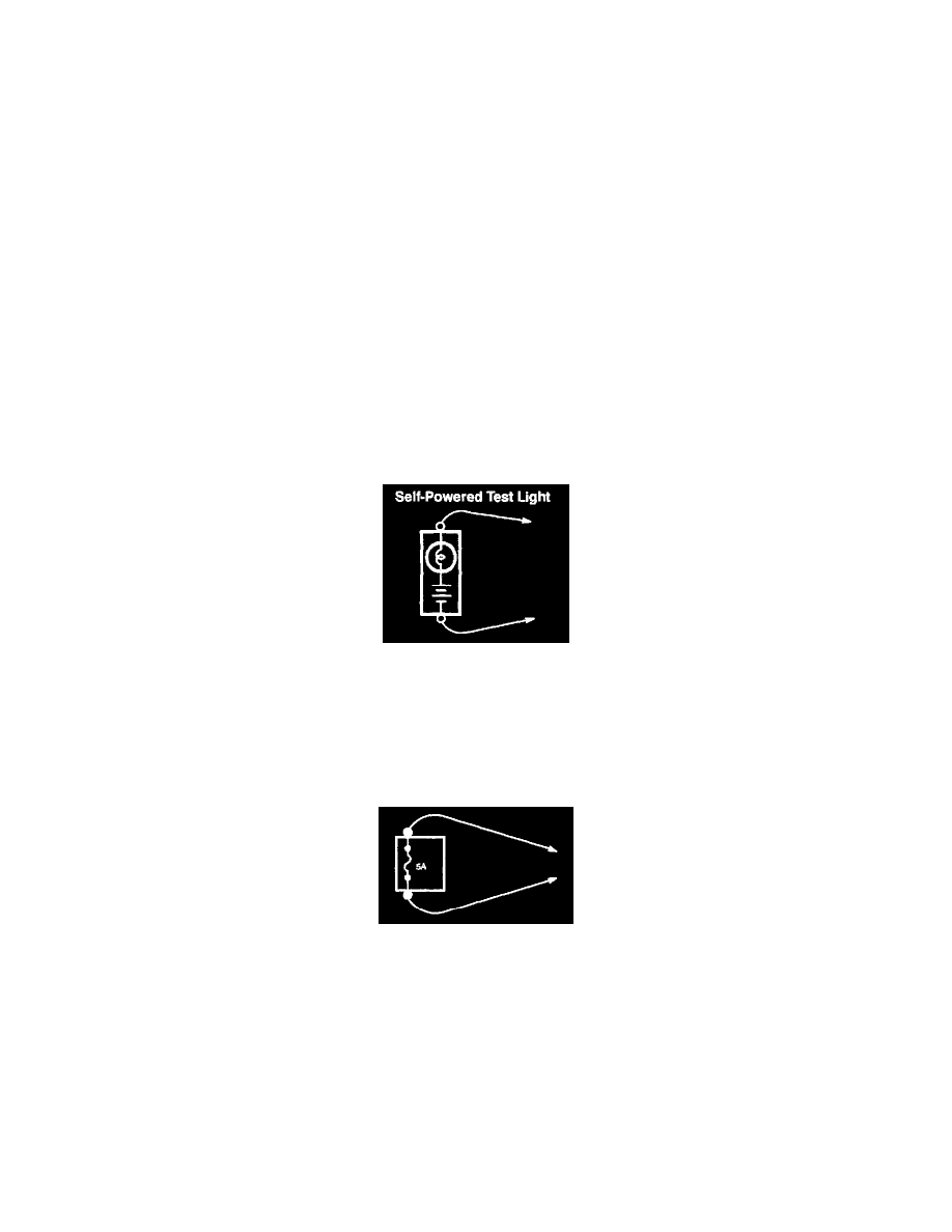
Self-Powered Test Light and Ohmmeter
Use a self-powered test light or ohmmeter to check for continuity. The ohmmeter shows how much resistance there is between two points along a circuit.
Low resistance means good continuity.
CAUTION: Never use a self-powered test light on circuits that contain solid-state devices. Damage to these devices may result.
Diodes and solid-state devices in a circuit can make an ohmmeter give a false reading. To find out if a component is affecting a measurement, take one
reading, reverse the leads, and take a second reading. If the readings differ, the component is affecting the measurement.
Circuits that contain solid-state devices should only be tested with a 10-megaohm or higher impedance digital multimeter.
A self-powered test light consists of a light bulb, battery and two leads. If the leads are touched together, the bulb will go on.
A self-powered test light is only used on an un-powered circuit. First disconnect the battery or remove the fuse that feeds the circuit you are working on.
Select two points along the circuit through which there should have continuity. Connect one lead of the self-powered test light to each point. If there is
continuity, the test light's circuit will be completed and the bulb will go on.
Fused Jumper Wire
Use a jumper wire to bypass an open circuit. A jumper wire is made up of an in-line fuse holder connected to a set of test leads. It should have a five
ampere fuse. Never use a jumper wire across any load. This direct battery short will blow the fuse.
Short Finder
Short finders are available to locate shorts to ground. The short finder creates a pulsing magnetic field in the shorted circuit and shows you the location
of the short through body trim or sheet metal. Its use is explained in the troubleshooting tests.
Testing For Voltage