
Trooper LS 2WD V6-3.5L (2001)
14. Remove the combination switch assembly with SRS coil.
Note: The SRS coil is a part of the combination switch assembly, which can not be replaced separately. Therefore, be sure not to remove the SRS
coil from the combination switch assembly.
15. Remove snap ring.
16. Remove cushion rubber.
17. Remove shift lock cable (for A/T).
18. Disconnect the starter switch harness connector located under the steering column, then remove lock cylinder assembly.
Installation
1. Install lock cylinder assembly.
2. Install shift lock cable (for A/T).
3. Install cushion rubber.
4. Install snap ring.
5. Install Combination switch and SRS coil assembly. After installation of combination switch assembly, connect the combination switch wiring
harness connector and the SRS 2-way connector located under the steering column.
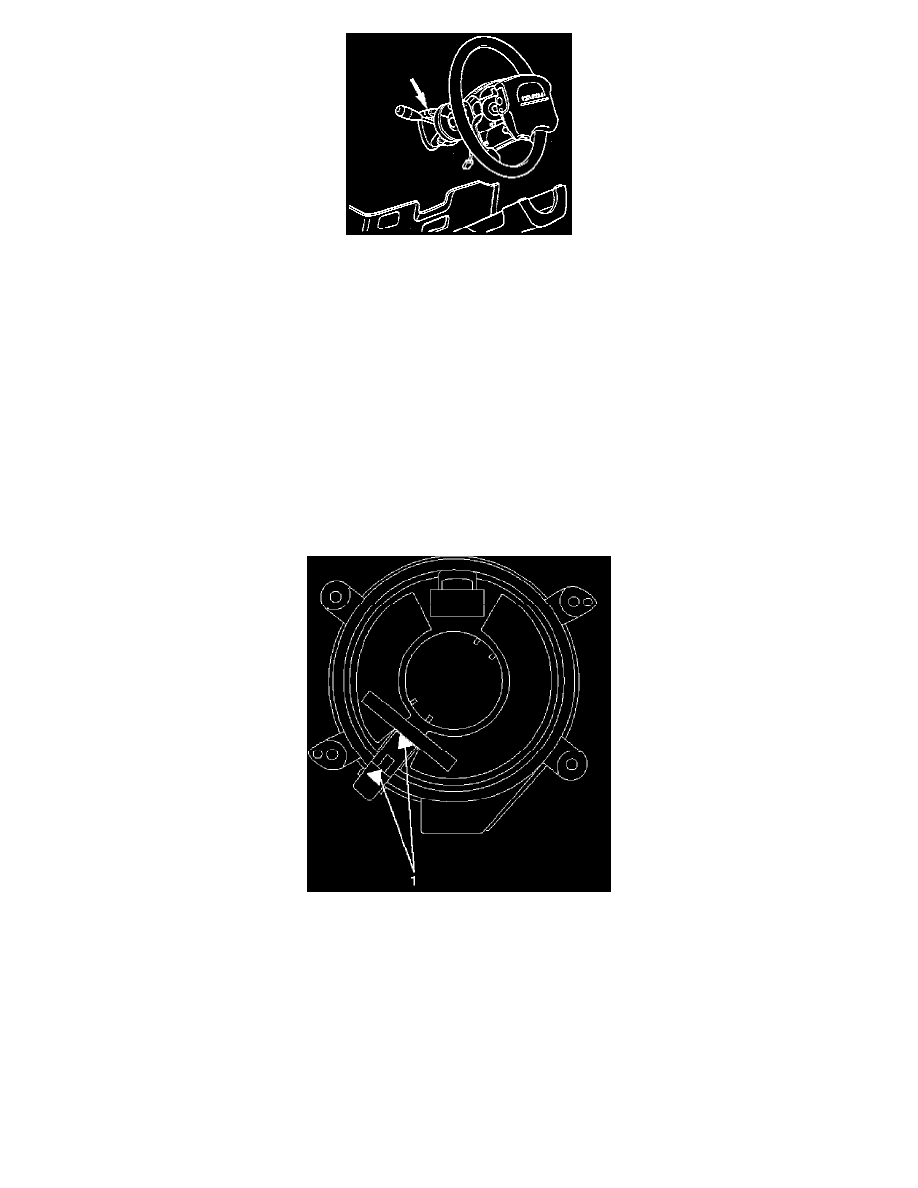
6. Turn the SRS coil counterclockwise to full, return about 3 turns and align the neutral mark.
Caution: When turning the SRS coil counterclockwise to full, stop turning if resistance is felt. Forced further turning may damage to the cable in
the SRS coil.