
Trooper S 2WD V6-3.5L (2001)
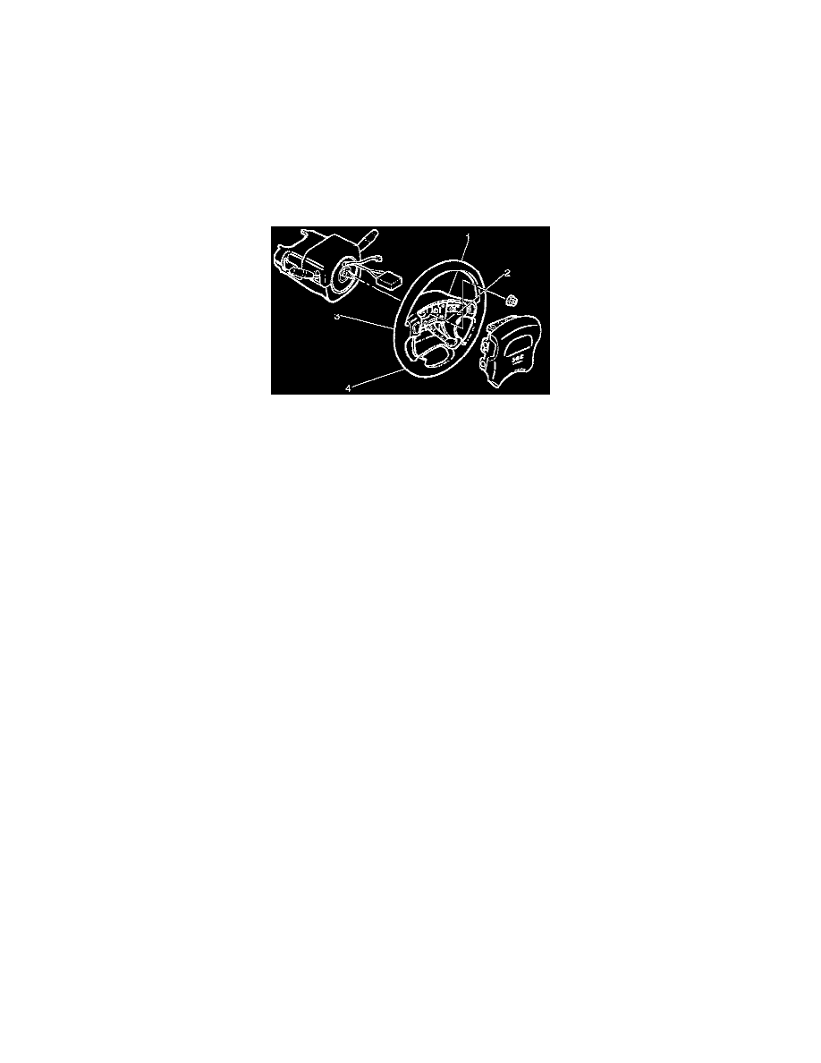
10. Support inflator module and carefully connect the module connector, then inflator module.
CAUTION:
^
Never use the air bag assembly from another vehicle. Use only the bag assembly for "UX".
^
The driver's air bag assembly (Inflator module) for 2000 model has different characteristic to the parts for 2000 model.
When replace the driver's air bag assembly, confirm the part number and use only the parts for 2000 model. (The driver's air bag assembly for
2000 model has "yellow" bar codes label. 2000 model has "white" bar codes label.)
NOTE: Pass the lead wire through the tabs on the plastic cover (wire protector) of inflator to prevent lead wire from being pinched.
11. Secure the inflator module with one bolt to relieve weight on the wire connector.
12. Tighten fixing bolts to specified sequence as illustrated.
Torque: 8 Nm (69 inch lbs.)
13. Install steering lower cover, then install the engine hood opening lever.
14. Install lower cluster assembly.
15. Connect the wiring harness connectors, then install front console assembly and install the transmission (for M/T) and transfer control lever knob.
16. Connect the yellow 2-way SRS connector located under the steering column.
17. Connect the battery "-" terminal cable.