
Trooper S 4WD V6-3.5L (2002)
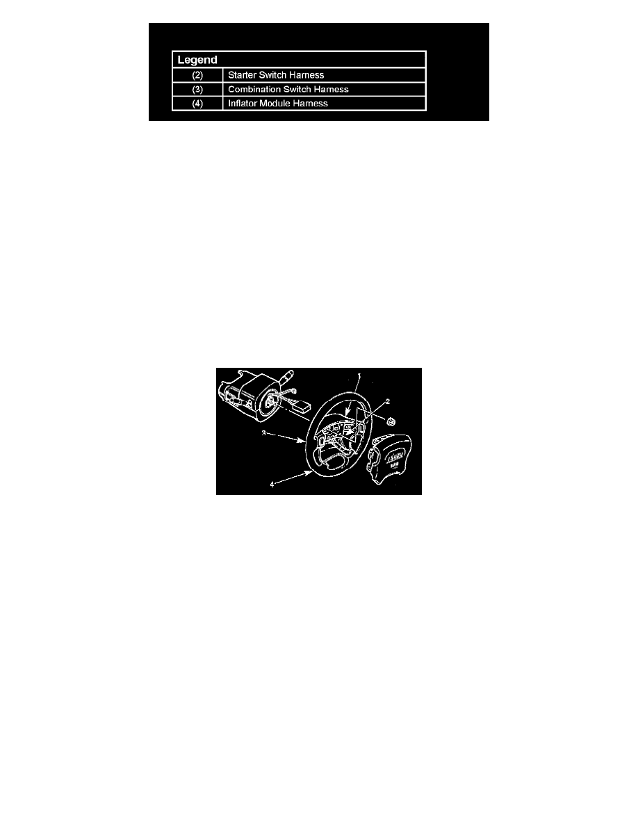
7. When installing the steering column cover, be sure to route each wire harness as illustrated so that the harnesses do not catch on any moving parts.
8. Install steering wheel by aligning the setting marks made during removal.
Caution: Never apply force to the steering wheel in direction shaft by using a hammer or other impact tools in an attempt to remove the steering
wheel. The steering shaft is designed as an energy absorbing unit
9. Tighten the steering wheel fixing nut to the specified torque.
Torque: 34 Nm (25 ft. lbs.)
10. Support inflator module and carefully connect the module connector, then install inflator module.
Caution:
^
Never use the air bag assembly from another vehicle. Use only the air bag assembly for "UX".
^
The driver's air bag assembly (Inflator module) for 1999 model has different characteristic to the parts for 1998 model.
When replace the driver's air bag assembly, confirm the parts number and use only the parts for 1999 model. (The driver's air bag assembly for
1999 model has "yellow" bar codes label. 1998 model has "white" bar codes label.)
Note: Pass the lead wire through the tabs on the plastic cover (wire protector) of inflator to prevent lead wire from being pinched.
11. Secure the inflator module with one bolt to relieve weight on the wire connector.
12. Tighten fixing bolts to specified sequence as illustrated.
Torque: 8 Nm (69 inch lbs.)
13. Install steering lower cover, then install the engine hood opening lever.
14. Install lower cluster assembly.
15. Connect the wiring harness connectors, then install front console assembly and install the transmission (for M/T) and transfer control lever knob.
16. Connect the yellow 2-way SRS connector located under the steering column.
17. Connect the battery "-" terminal cable.