
Trooper S 4WD V6-3.5L (2002)
This test measures voltage in a circuit. When testing for voltage at a connector, you may not have to separate the two halves of the connector. Instead,
probe the connector from the back. Always check both sides of the connector because dirt and corrosion between its contact surfaces can cause electrical
problems.
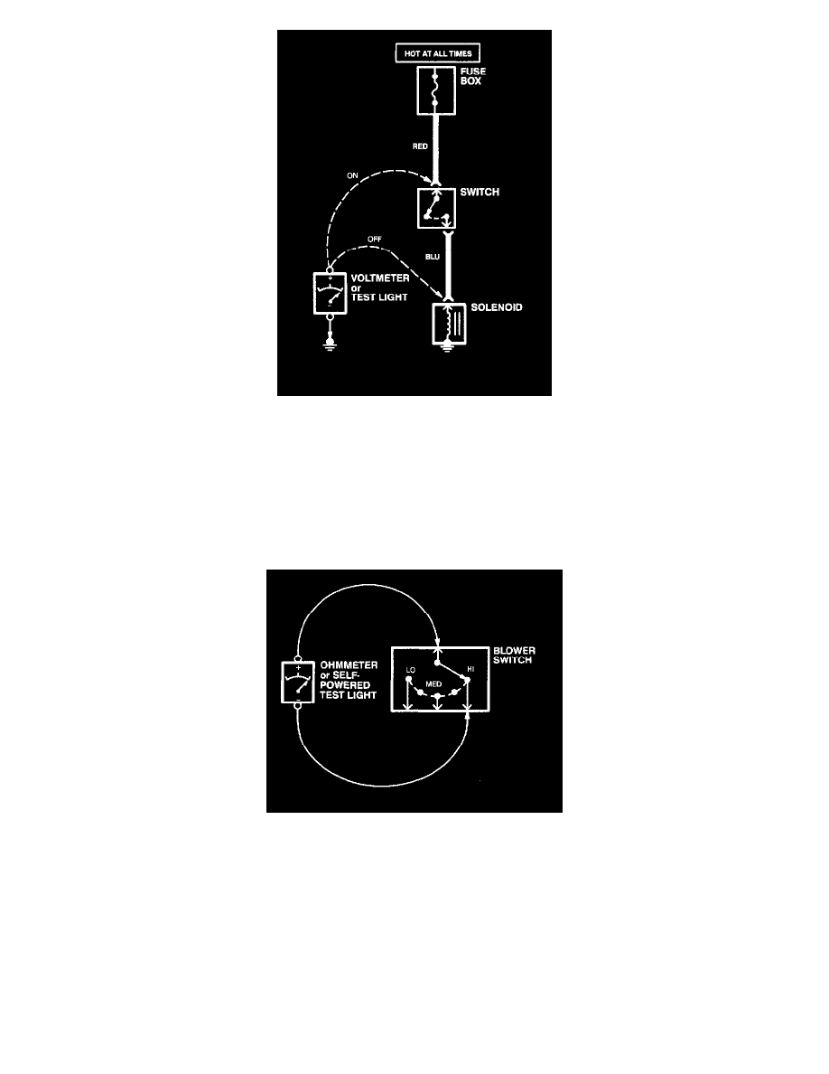
1. Connect one lead of test light to known good ground, or if you are using a voltmeter, be sure you connect its negative lead to ground.
2. Connect the other lead of the test light or voltmeter to the point you want to check.
3. If the test light glows, there is voltage present. If you are using a voltmeter, note the voltage reading. It should be within one volt of measured
battery voltage. A loss of more than one volt indicates a problem.
Testing For Continuity
This test checks for continuity within a circuit. When testing for continuity at a connector, you may not have to separate the two halves of the connector.
Instead, probe the connector from the back. Always check both sides of the connector because dirt and corrosion between contact surfaces can cause
electrical problems.
1. Disconnect the negative cable from the car battery.
2. If you are using an ohmmeter, hold the leads together and adjust the ohmmeter to read zero ohms.
3. Connect one lead of self-powered test light or ohmmeter to one end of the part of the circuit you wish to test.
4. Connect the other lead to the other end.
5. If the self-powered test light glows, there is continuity. If you're using an ohmmeter, low or no resistance means good continuity.
Testing For A Voltage Drop