
Trooper S 4WD V6-3.5L (2002)
4. Strip the insulation as necessary.
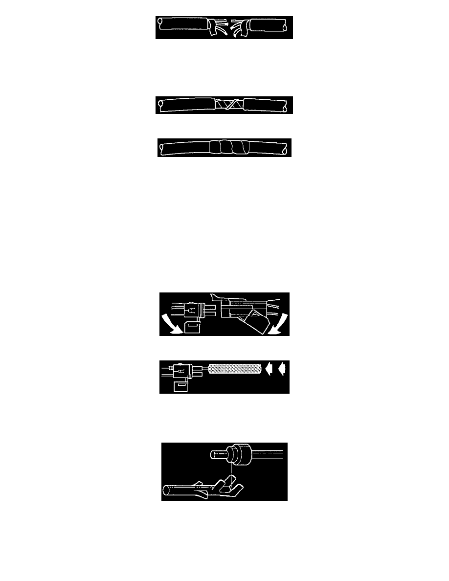
INSTALLATION PROCEDURE
1. Splice the wires using splice clips and rosin core solder.
2. Wrap each splice to insulate.
3. Wrap the splice with mylar and with the drain (uninsulated) wire.
4. Tape over the whole bundle to secure.
Weather-Pack Connector
Weather-Pack Connector
Tools Required
J 28742-A Weather-Pack II Terminal Remover
Removal Procedure
A Weather-Pack connector can be identified by a rubber seal at the rear of the connector. This engine room connector protects against moisture and dirt,
which could from oxidation and deposits on the terminals. This protection is important, because of the low voltage and the low amperage found in the
electronic systems.
1. Open the secondary lock hinge on the connector.
2. Use tool J 28742-A or the equivalent to remove the pin and the sleeve terminals. Push on J 28742-A to release.
NOTE: Do the use an ordinary pick or the terminal may be bent or deformed. Unlike standard blade terminals, these terminals cannot be straightened
after they have been improperly bent.
3. Cut the wire immediately behind the cable seal.
Installation Procedure
Make certain the connectors are properly seated and all of the sealing rings are in place when you reconnect the leads. The secondary lock hinge
provides a backup locking feature for the connector. The secondary lock hinge is used for added reliability. This flap should retain the terminals even if