
Trooper S 4WD V6-3.5L (2002)
wheel. Failure to do so will cause the coil assembly to become uncentered which will cause damage to the coil assembly.
5. Remove the transmission (for M/T) and transfer control lever knob and disconnect the wiring harness connectors, then remove front console
assembly.
6. Remove lower cluster assembly.
7. Remove the engine hood opening lever and steering lower cover.
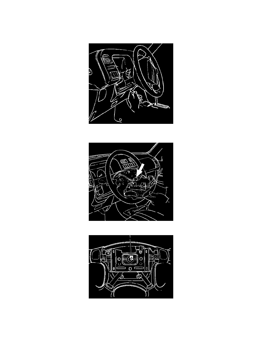
8. Loosen the inflator module fixing bolt from behind the steering wheel assembly using a TORX (I) driver or equivalent until the inflator module
can be released from steering assembly.
9. Disconnect the yellow 2-way SRS connector located behind the inflator module.
10. Apply a setting mark (1) across the steering wheel and shaft so parts can be reassembled in their original position.