
VehiCROSS 4WD V6-3.5L (1999)
Vehicle Speed Sensor: Diagnostic Aids
Five-Step Troubleshooting
The following five-step troubleshooting procedure is recommended:
1. Verify the Problem
Check the problem circuit's operation to be sure you understand what's wrong. Do not begin disassembly or testing until you have narrowed down
the possible causes.
If the system you are troubleshooting has a built-in self-diagnostic system.
2. Analyze the Circuit Schematic
Analyze the schematic. Read the Circuit Operation text if you do not understand how the circuit should work. Check circuits that share the wiring
with the problem circuit. The names of circuits that share the same fuse, ground, switch, etc., are included on each electrical schematic. Shared
circuits are also shown on Power Distribution, Ground Distribution, Dash Fuse Box, and Lighting Switch Details pages. Try to operate the shared
circuits. If these circuits work, then the shared wiring is OK. The cause must be within the wiring used only by the problem circuit. If several
circuits fail at the same time, chances are the power (fuse) or ground circuit is faulty.
3. Find the Cause
^
narrow down the possible causes
^
use the troubleshooting hints
^
make the necessary measurements as given in the troubleshooting procedures
^
before you replace a component, check power, signal, and ground wires at the component harness connector
4. Repair the Problem
Once the specific problem is identified, make the repair. Be sure to use proper tools and always observe safe procedures.
5. Check the Repair
Check the repaired circuit's operation in all modes to make sure that you've fixed the entire problem. If the problem was a blown fuse, test all
circuits on that fuse. Make sure that no new problems turn up.
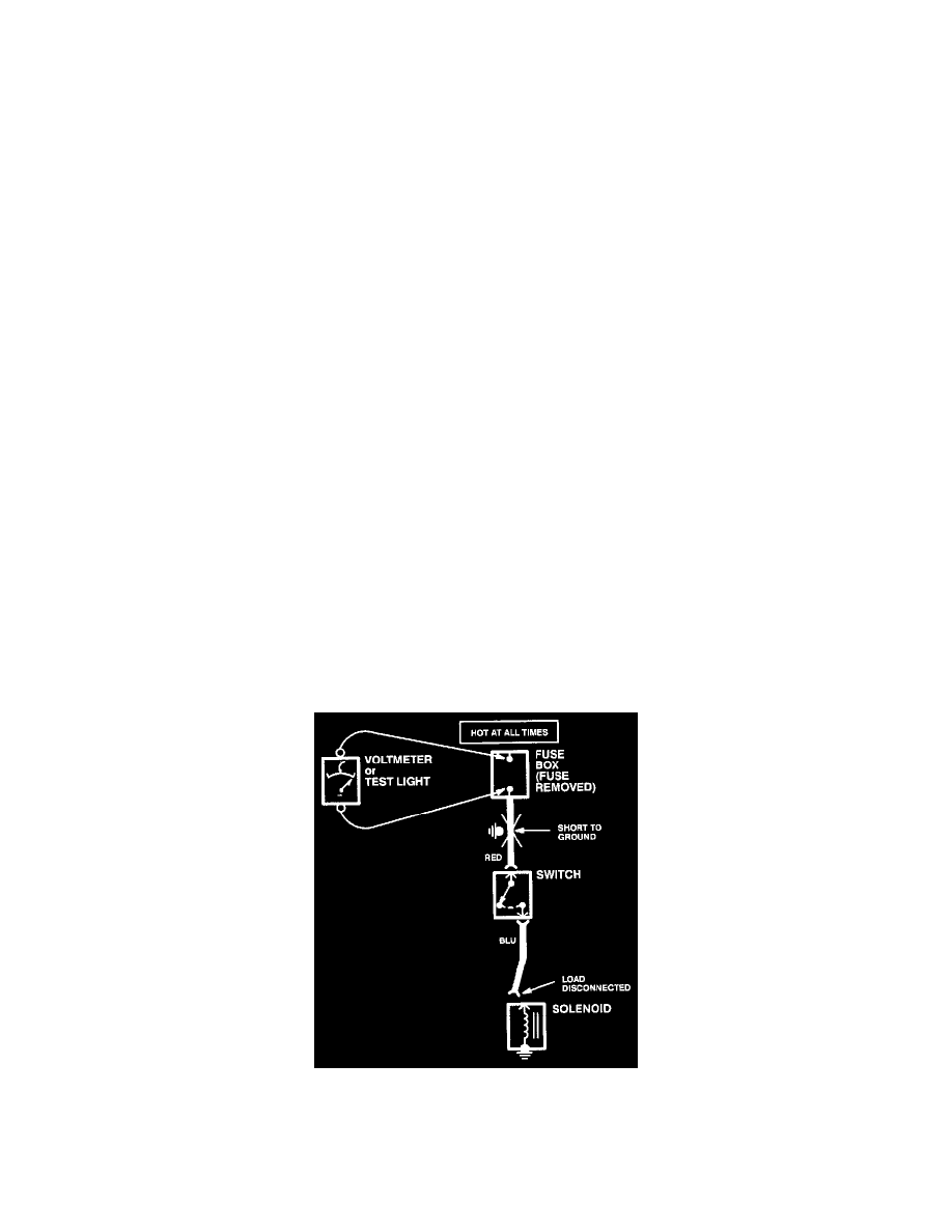
Testing For A Short to Ground With A Test Light Or Voltmeter
1. Remove the blown fuse and disconnect the load.
2. Connect a test light or voltmeter across the fuse terminals. Make sure voltage is being applied to the battery side fuse terminal. Check schematic to
see if the ignition switch needs to be in RUN.
3. Beginning near the fuse box, wiggle the harness. Continue this at convenient points about six inches apart while watching the test light or
voltmeter.
4. When the test light blinks or the voltmeter needle moves, there is a short to ground in the wiring near that point.
Testing For A Srt to GND Wth A Self-Powered Tst Lht or Ohmmeter
1. Remove the blown fuse and disconnect the battery and load.
2. Connect one lead of a self-powered test light or ohmmeter to the fuse terminal load side.