
VehiCROSS 4WD V6-3.5L (1999)
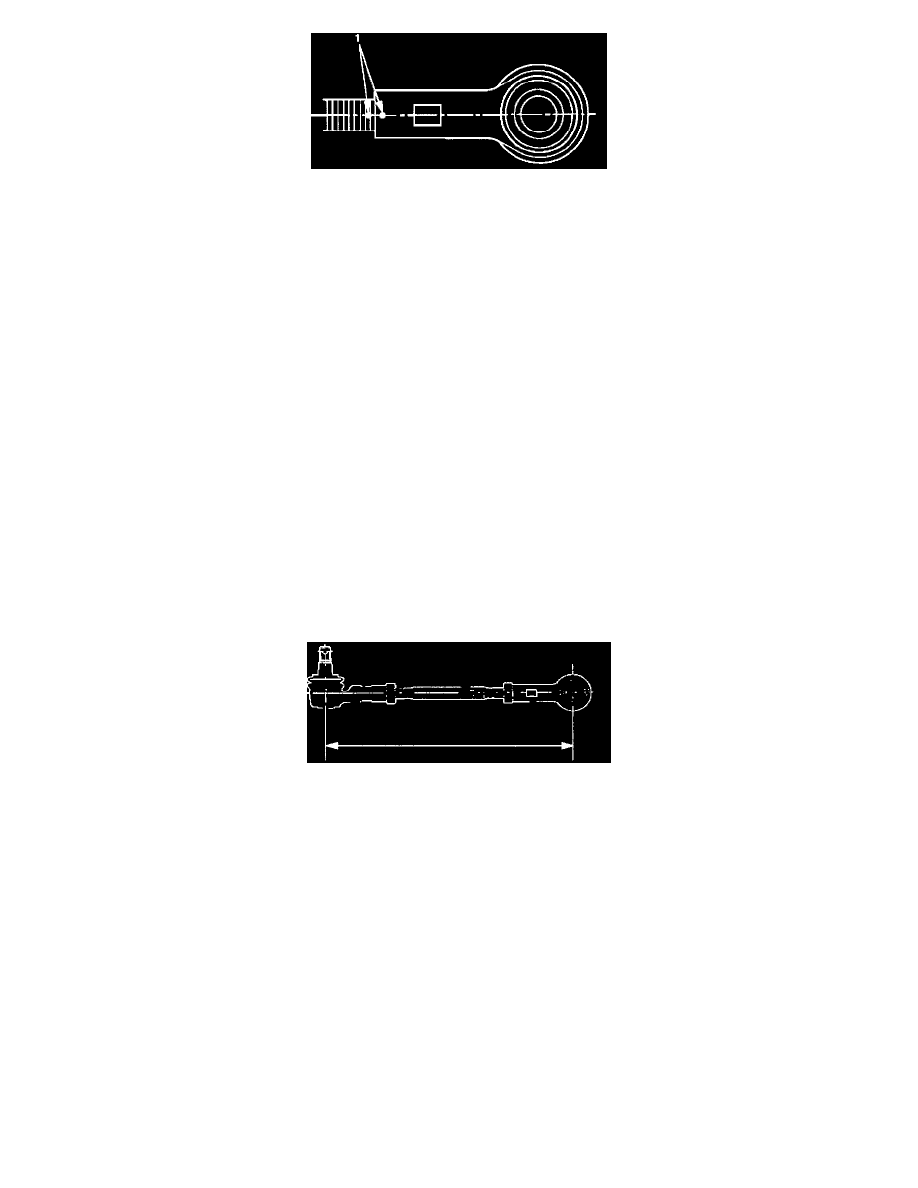
7. Apply setting marks (1) to ensure reassembly of the parts in their original position, then remove inner rod end.
INSPECTION AND REPAIR
Make necessary correction or parts replacement if wear, damage, corrosion, bending, deteriorations or any other abnormal condition are found through
inspection.
Check the following parts:
-
Rod end assembly
-
Ball joint (Boot, screws and tapered surfaces)
INSTALLATION
1. Install inner rod end and align the setting marks applied during disassembly.
2. Tighten the inner lock nut to specified torque.
Torque: 118 Nm (87 ft. lbs.)
NOTICE: For either outer rod, the screw on the right side of the vehicle is threaded counterclockwise.
3. Install outer rod end assembly and align the setting marks applied during disassembly.
4. Tighten the outer lock nut to specified torque.
Torque: 118 Nm (87 ft. lbs.)
5. Install knuckle arm nut and cotter pin then tighten the nut to the specified torque, with just enough additional torque to align cotter pin holes.
Install new cotter pin.
Torque: 98 Nm (72 ft. lbs.)
6. Install center track rod and nut and cotter pin then tighten the nut to the specified torque, with just enough additional torque to align cotter pin
holes. Install new cotter pin.
Torque: 98 Nm (72 ft. lbs.)
NOTICE: If replacing the track rod, adjust the new track rod length.
Rod length: 328.3 mm (12.93 inch)
NOTICE: Adjust the toe-in.