
Majestic L6-4.0L (1990)
Engine Control Module: Description and Operation
General Description
The AJ6 4.OL EMS is microprocessor based using the Lucas 15 CU ECM as the heart of the system. The 15 CU ECM microprocessor runs at 2.0
MHz. The ECM uses discrete components plus analog-to-digital circuits to interface between the microprocessor and the input sensors and output
devices, Software, programmed into an EPROM, is divided into "control code" and "data" (engine calibration). Control code is common to all
engine specifications; data is written for specific market specifications such as US EPA emission regulations.
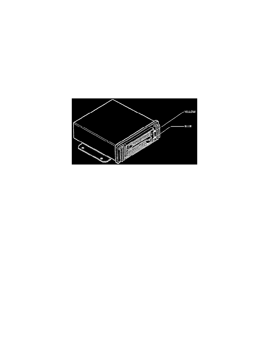
The ECM contains two double sided printed circuit boards. One is a low power board and the other is a high power board. The YELLOW and
BLUE 25-way connectors are therefore referred to as the low and high power connectors respectively. Most of the input signals from engine
mounted sensors, and interfaces with other systems are located on the low power (Yellow) connector. The high power connector (Blue), mainly
serves outputs such as fuel injector drive and relay activation. Inputs and outputs are included with the wiring diagrams.
The ECM receives sensor inputs and feedbacks, which are used to determine the optimum strategy for the prevailing conditions. The ECM's
strategy has 256 memory locations containing injector pulse durations and ignition timing angles for 16 different engine loads (engine load sites)
and 16 different engine speeds (engine speed sites). Canister purge, idle speed, air injection and exhaust gas recirculation are controlled by the
ECM from stored strategies.
Engine Control Module