
Sovereign L6-4.0L (1991)
Brake Fluid Pump: Description and Operation
PUMP MOTOR OPERATION
With the pressure in the hydraulic accumulator below 140 bar the motor will switch on.
When the ignition is switched on battery power is supplied to the relay coil, if the pressure in the hydraulic accumulator is below 140 bar, the coil will
be grounded. Battery power is then supplied to the pump motor via the closed contacts of the relay and a 30 amp fuse. The motor operates till a
pressure of 180 bar is achieved. Having reached a pressure of 180 bar the pressure switch contacts open de-activating the relay thus switching off the
pump motor. When the pressure drops to 140 bar the pressure switch closes, switching on the pump motor so that the system pressure is maintained at
between 140 to 180 bar.
Hydraulic Pump And Accumulator
MOTOR PUMP UNIT
With the motor pump unit, an independent energy supply is obtained by means of a motor and a pump which generates hydraulic energy, and
accumulates the pressure energy in a hydraulic accumulator. From the hydraulic accumulator the pressure supply for the dynamic circuit of the rear
wheel brakes, the hydraulic brake booster and the static circuit of the front wheel brakes is provided during a braking with ABS control.
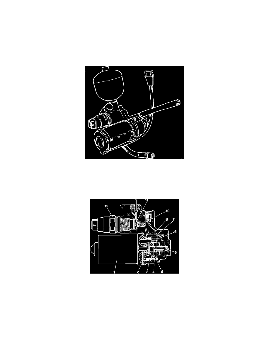
Hydraulic Pump Assembly
The motor (1) drives via a coupling (2) a rotor (3) which includes two pistons (4) and two balls (5) which move in an eccentric ring (6). Brake fluid is
drawn via the suction channel (7), a filter (8), through the control shaft (9) on the upper side of the lower piston. The rotation causes a reduction of
space due to the eccentric ring and ball. The piston is moved towards the control shaft and a pressure is generated.
The pressure opens a check valve (10), is transmitted to the accumulator and to the annular chamber of the control piston in the booster.
Simultaneously the pressure acts on the tappet (11) of the combined pressure warning switch (12) and moves it till the system pressure of 180 bar is
achieved, the pressure switch in the combined pressure switch switches the motor off.
The hydraulic system is protected against damage by the pressure control valve which releases pressure at 210 bar.