
Sovereign L6-4.0L (1991)
Hydraulic Control Assembly - Antilock Brakes: Description and Operation
Valve Block
ABS Brake Master Cylinder
VALVE BLOCK
The valve block contains three pairs of solenoid valves, one pair for each of the front brakes and one pair for the rear brakes. Each pair contain an
outlet and an inlet valve. The valves are electronically operated by signals from the ECM. During braking with ABS control, the electronic control
module provides a voltage to the inlet and outlet solenoid valves, which influence the hydraulic pressure to the brakes. The control to the rear brakes
is determined by the wheel which first shows a tendency to lock. The brake pressure at both rear wheels is thus determined by the wheel having the
lowest friction coefficient.
This ensures that in the case of braking on a surface with low friction coefficient neither of the rear wheels will lock.
All the valves with the exemption of the main valve have a common ground point which is connected to pin 11 of the control module.
The ground connection pin 11 is known as the reference ground, via this connection the electronic control module receives test pulses for the valves.
NOTE:During normal braking the anti-lock system will not be activated. However, if the braking force applied is sufficient to overcome tire/road
adhesion, the anti-lock system will automatically be activated preventing the road wheel from locking.
With no current flowing through the inlet solenoids the valves are open so that during braking the brake pressure can be applied direct to the wheel
brakes.
With no current flowing through the outlet solenoids the valves are closed and disconnect the wheel brakes from the reservoir.
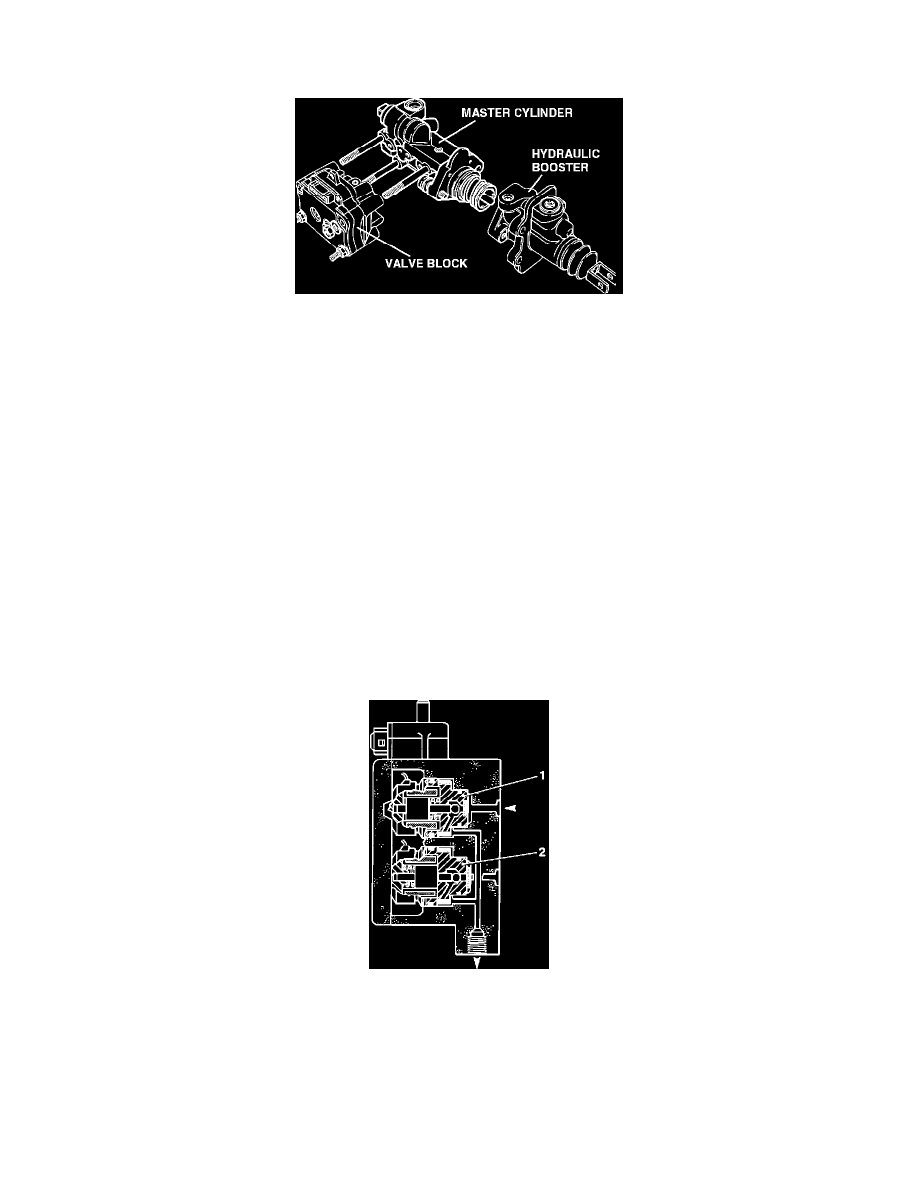
Valve Block
To maintain pressure, the outlet valve (1) stays closed, and the inlet valve (2) to a 'wheel with a tendency to lock' closes, ensuring the brake pressure to
that wheel cannot be increased.
To decrease pressure the inlet valve closes and the outlet valve opens. The brake pressure to the wheel is decreased.
To increase the pressure to the wheel the inlet valve opens and the outlet valve closes and the brake pressure to the wheel is again increased almost up
to the locking pressure limit.