
Sovereign L6-4.0L (1991)
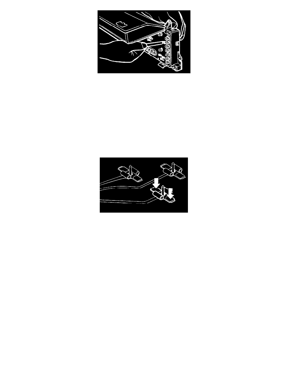
Fig 6
Displace and remove the veneer panel. The LCD module is attached to the veneer panel, and with caution may be removed as a complete, assembly.
CAREFULLY, remove oil/water temperature gauge set, gently easing the pins out of the printed circuit crimps (Fig 6). To prevent widening crimp
connections, gauge pairs should be kept square to the Instrument Pack moulding whilst removing.
Repeat for the battery/fuel gauge set
Repeat for the speedometer/tachometer gauge set.
Displace and remove the flexible printed Circuit.
NOTE: Individual gauge movements CAN NOT be serviced, pointers and can location screws should not be removed. Gauges should not be placed
face down.
Align new flexible printed circuit to instrument pack. Align and fit speedometer/tachometer gauge set to instrument pack. Take care not to damage
gauge needles.
Fig 7
Ensure gauge set is inserted square to pack and flexible printed circuit and CAREFULLY push the gauge pins through the printed circuit. DO NOT
press down on the crimps, distortion may occur. Press down on the flat tangs (set at right angles to the crimps) as shown in Fig 7
NOTE: Take care not to damage crimps or flexible printed circuit. If damage occurs or problems arise due to loose crimp connections, renew the
flexible printed circuit.
Repeat for the battery/fuel gauge set.
Repeat for the oil/water temperature gauge set.
Before fitting veneer panel, carefully return all gauge needles to "STOP PIN" position.
Align and fit veneer panel/LCD module assembly. Fit and tighten centre securing screw.
Fit the cowl/lens assembly.
Fit and tighten the six remaining veneer panel securing screws.
Fit and fully seat warning bulbs, ensuring correct colour type is inserted at correct location (the 8 white bulb/ holders are for gauge illumination, the
remaining 24 are for warning indication only).
Connect the flexible printed circuit multi-plug to the LCD unit.
Carefully fit electronics pack over the flexible printed circuit connections and locate into hinges.
Pivot pack downwards and fit into securing clips.
Fit the flexible printed Circuit to the edge-connectors, by positioning holes in flexible printed circuit membrane over the connector-latch locating pips
and sliding latch to the fully closed position
Align and fit the back cover to the electronics pack. Fit and tighten the securing screws.
Fit the cowl-housing to the pack. Fit and tighten the cowl-housing securing screws.