
Vanden Plas L6-3.6L (1988)
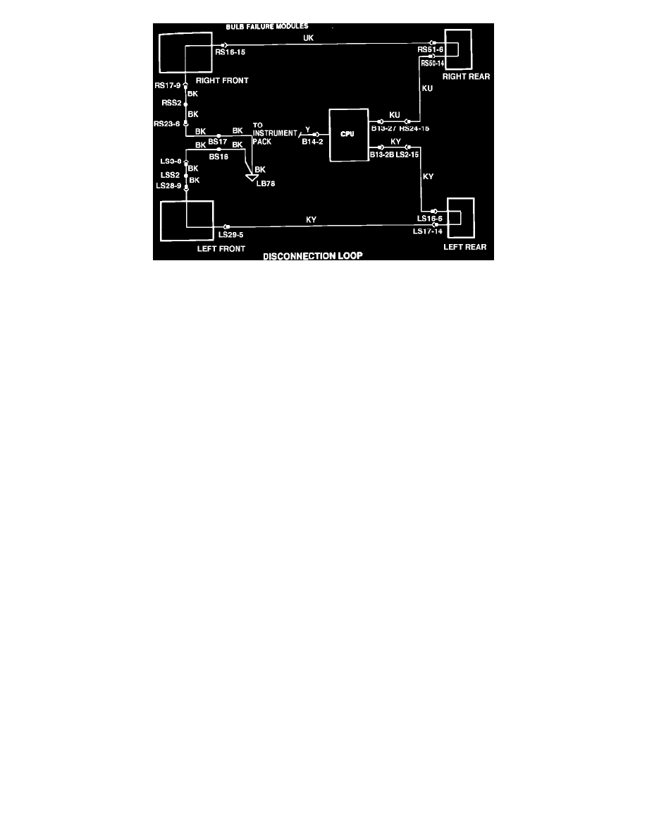
FIGURE 2
3.
Disconnection Loop (Fig. 2)
The VCM will display "Bulb Failure" if a connector between a bulb failure module and the CPU is not connected (open circuit). The disconnected
loop maintains a constant ground at the appropriate pins of the CPU via the bulb failure modules. When the ground is broken, the CPU switches
battery voltage to the yellow wire that terminates at instrument pack via connector LB 14 pin 2. This illuminates the "Bulb Failure" display.
WIRING COLOR CODE
N
BROWN
Y
YELLOW
B
BLACK
O
ORANGE
W
WHITE
S
SLATE (GRAY)
K
PINK
L
LIGHT
G
GREEN
U
BLUE
R
RED
P
PURPLE
When a wire has two color code letters, the first letter indicates the main color and the second letter indicates the tracer color.
EXAMPLE:
WK = white with a pink tracer. PGS = purple with a green and slate tracer