
Vanden Plas L6-3.6L (1988)
Center Mounted Brake Lamp Relay: Technical Service Bulletins
Electrical Relays - Locations
ELECTRICAL
SECTION:
86
No:
35
Model:
XJ6 3.6 Date: JULY, 1988
KEY POINTS:
ELECTRICAL RELAY LOCATIONS
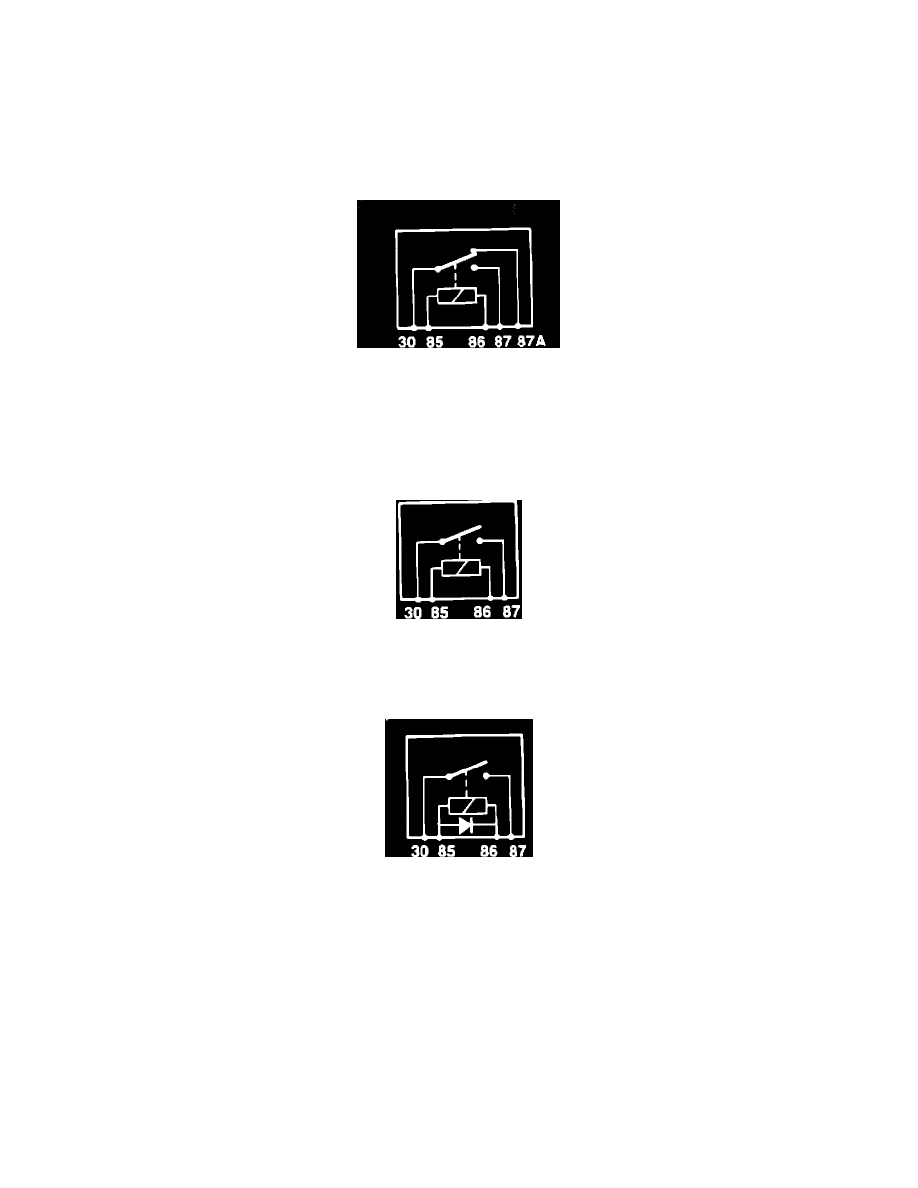
FIGURE 1
The XJ6 3.6 incorporates 34 replaceable relays, most of which are grouped into the following categories:
1.
Change Over Relay (C/O). This is a green relay (DBC 2483) with two output terminals, 87 and 87A (Fig. 1). Relay switch rests on contact 87A,
and when activated changes to terminal 87 (Fig. 1).
1a. Normally Closed Relay (N/C). This is a green relay (DBC 2483) with one output terminal, 87A. When activated, relay has no output (Fig. 1).
FIGURE 2
2.
Normally Open High Current Relay (N/O-H). This is a yellow relay (DBC 2486) with one output terminal, 87 (Fig. 2).
3.
Normally Open Low Current Relay (N/O-L). This is a black relay (DBC 2484) with one output terminal, 87 (Fig. 2).
FIGURE 3
4.
Normally Open Low Current Relay with Diode (N/O-L/D). This can be a blue or black relay (JLM 771) with one output terminal, 87 (Fig. 3)
Relay Location and Connector Information:
Right Side of Trunk. (Relay 1, 2, 3, 4, 5) (For access, remove right side trim panel)
5.
RELAY NAME RELAY TYPE CONNECTOR COLOR CONNECTOR NO.
1.
Trunk Lock Relay C/O Yellow RS 40
2.
Trunk Unlock Relay C/O Blue RS 39
3.
Antenna Down Relay C/O Black RS 38
4.
Antenna Up Relay C/O Green RS 37
5.
Heated Rear Window Relay N/O-L Red RS 36
Right Side of Trunk (Relay 6) (For access, remove right side trim Panel)
RELAY NAME
RELAY TYPE CONNECTOR COLOR CONNECTOR NO.
6.
High Mounted Stop N/O-L Yellow RS 79 Lamp Relay