
Vanden Plas L6-4.0L (1990)
Control Module: Diagrams
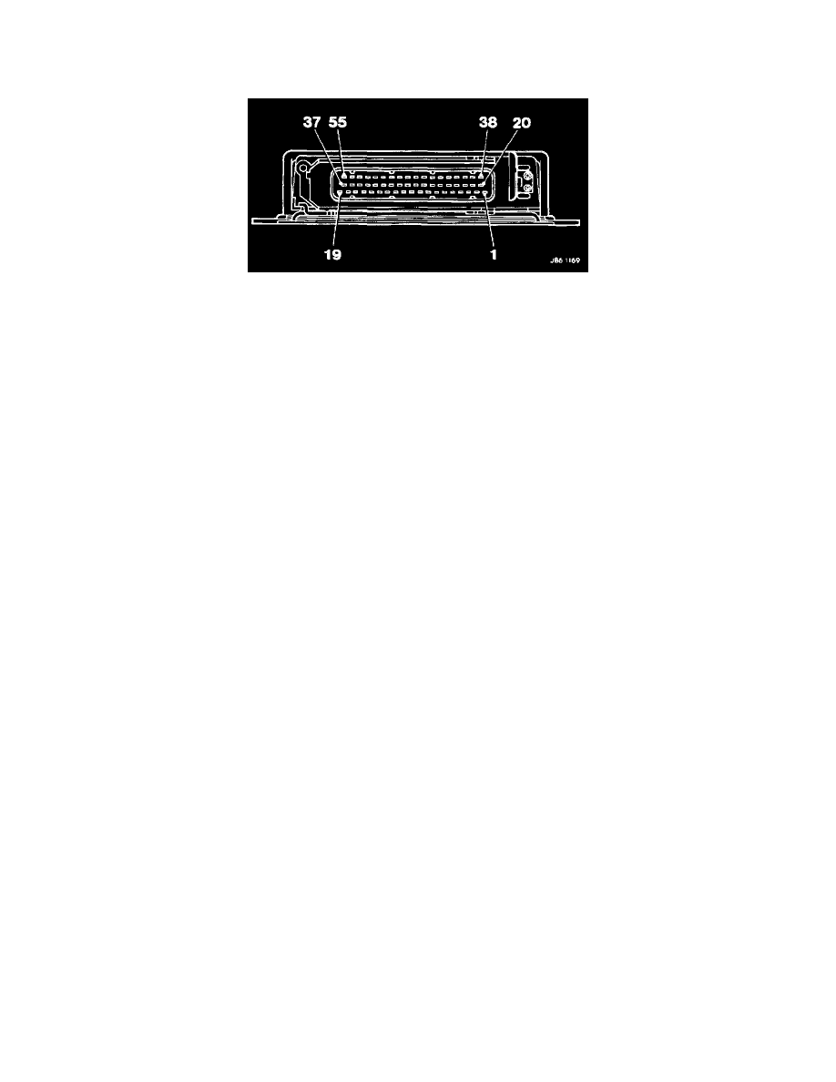
TRANSMISSION CONTROL MODULE CONNECTIONS - PIN LOCATIONS
PIN FUNCTION
1.
Ignition power supply (B+)
2.
Vehicle speed sensor (B+)
3.
Engine speed sensor
4.
-
5.
Solenoid valve MV1
6.
Pressure control valve
7.
Digitial ground
8.
Throttle potentiometer signal
9.
Pin code 1 - catalyst
10.
Pin code 3
11.
-
12.
-
13.
-
14.
Position code Y
15.
Diagnostic L-line
16.
System fault indicator
17.
-
18.
-
19.
Solenoid valves supply
20.
Vehicle speed sensor screen
21.
Injector time (torque signal)
22.
-
23.
-
24.
Solenoid valve MV2
25.
Torque control (select)
26.
Powerground
27.
-
28.
Pin code 2
29.
-
30.
-
31.
-
32.
Torque control
33.
Position code Z
34.
-
35.
-
36.
-
37.
-
38.
Vehicle speed sensor (B+)
39.
Permanent battery supply
40.
-
41.
'Kick-down' switch
42.
Solenoid valve lock-up
43.
Program push button (sport)
44,
Throttle potentiometer ground
45.
Throttle potentiometer supply
46.
-
47.
-