
Vanden Plas L6-4.2L (1982)
Service tool: Steering joint taper separator JD 24
-
Jack up front of car and place on stands.
-
Remove front wheel[s].
-
Place jack beneath front spring seat pan and raise sufficient to relieve stub axle carrier of spring pressure.
-
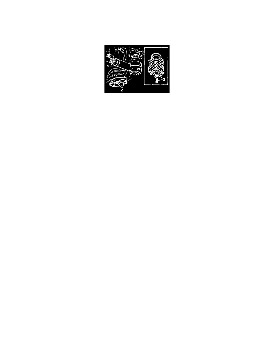
Remove self-locking nut and washer [1] securing steering tie rod ball-joint.
-
Separate tie-rod from steering arm using service tool JD 24.
-
Lift hub and stub axle carrier assembly to reveal any free play in lower ball-joint.
-
Bend back tab washers, remove four screws [2] securing ball pin cap to stub axle carrier.
-
Detach ball pin cap, shims and socket from stub axle carrier.
-
Clean and examine all parts for wear.
CAUTION: In order to obtain correct adjustment of ball joint it is necessary to shim to correct clearance. Excessive wear on ball pin and sockets must
not be adjusted by shims. Worn parts must be renewed.
-
Remove shims one by one until ball pin is tight in its socket with screws fully tightened.
NOTE:shims are available in 0.05 mm (0.002 in) and 0.10 mm (0.004 in) thicknesses.
-
Remove screws. ball pin cap, shims and socket.
-
Add shims to the value of 0.10 mm to 0.15 mm (0.004 in to 0.006 in).
-
Lightly grease ball pin and socket.
-
Refit socket ball pin cap and new tab washers.
-
Refit and tighten screws [2] to correct torque figure.
When correctly adjusted. hub and stub axle carrier can be pivoted with a very slight drag. Turn up tab washers and charge joint with correct grease.
-
Replace nut and washer [1] refit wheel[s] and lower car.
NOTE:The bolts securing the lower ball pin cap to the stub axle camber may on some vehicles be in a mixed condition. i.e. the head of the bolts are of
different thicknesses 7.94 mm (0.3125 in) and 4.76 mm (0.1875 in).
The bolts with a head thickness of 7.94 mm (0.3125 in) are fitted on production to the inboard holes of the lower ball pin cap.
It is important that if any of these bolts are removed during service, they should be replaced in the correct position.
1. Inboard bolts - bead thickness 7.94 mm (0.3125 in)
2. Outboard boos - head thickness 4.76 mm (0.1875 in)