
XJ-6 L6-36L (1989) Air Flow Meter/Sensor Component Diagrams
Air Flow Meter/Sensor: Testing and Inspection
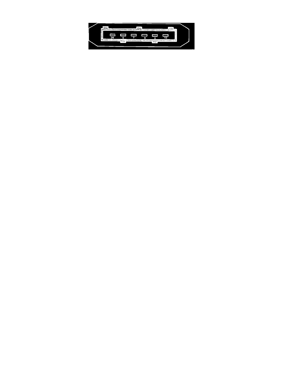
Airflow Meter Connector
PREPARATION
1.
Unplug airflow meter electrical connector. Connect pin 36 to the negative side of a suitable power supply and pin 9 to the positive side.
2.
Set power supply to 14V.
3.
Connect voltmeter positive lead to pin 7 and negative lead to pin 6. Select a voltage range as close to 0 - 10V as your meter permits.
TEST 1
NOTE: Make this test with no air moving through airflow meter. Ideally, each end of the meter should be covered.
1.
If voltmeter reading is 0.4V ± 0.2V, airflow meter is okay.
2.
If voltmeter reading is 0V, an open circuit exists. Airflow meter should be replaced.
3.
If voltmeter reading is greater than 0.7V, airflow meter calibration is incorrect, the module is defective or hot or cold sensor has become detatched
from its connections. Airflow meter should be replaced.
TEST 2
NOTE: For this test, read voltages that result from blowing one hard blast of air through airflow meter in normal direction of flow.
1.
If voltmeter reading rises to 1.5V, then falls back to 0.4V ± 0.2V (same result as TEST 1, step 1), airflow meter is okay.
2.
If voltmeter reading is 0V, an open circuit exists. Airflow meter should be replaced.
3.
If voltmeter reading is greater than 0.7V, airflow meter calibration is incorrect, the module is defective or hot or cold sensor has become detatched
from its connections. Airflow meter should be replaced.
4.
If voltmeter reading exceeds 5V, airflow meter calibration is incorrect or the module is defective. Airflow meter should be replaced.