
XJ-6 L6-4.2L (1983)
Air Flow Meter/Sensor: Description and Operation
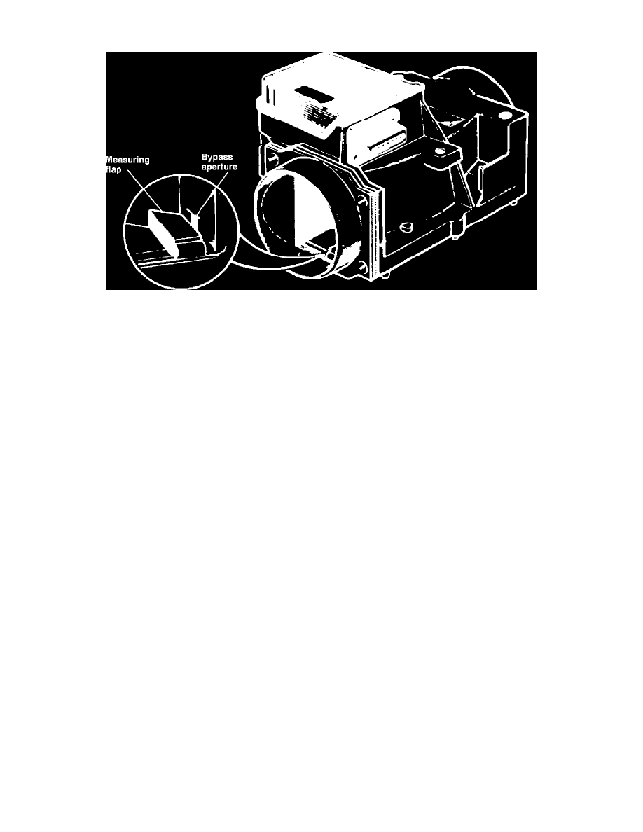
Fig. 2 Air flow meter
The air flow meter, Fig. 2, measures the quantity of intake air, and sends a signal to the control unit so the base pulse width can be determined for correct
fuel injection.
The air flow meter is provided with a flap in the air passage. As the air flows through the passage, the flap rotates and the angle of rotation is
electronically monitored to measure air flow rate. The flap is able to rotate to an angle where an equilibrium can be maintained between the air flow
pressure and the return torque of the coil spring. The damper chamber and compensating plate are provided as a damper for the flap so the flap will not
be disturbed by pulsation in manifold vacuum during operation. The compensating plate is interlinked with the flap, and as the flap rotates, the
compensating plate rotates in the damper chamber providing a small clearance between the chamber wall.
During idling, when the amount of intake air is small, the air flows parallel with the flap through the bypass port so the specified intake air flow can be
provided correctly. The bypass port has been factory adjusted, but can be adjusted further, if necessary, by turning the air bypass screw.
The fuel pump relay contact is provided in the potentiometer section of the air flow meter. This contact remains in the ``Off'' position when the flap is not
actuated. The relay turns ``On'' when the flap turns 8°, and electric current flows through the fuel pump relay to the fuel pump.