
XJ-6 L6-4.2L (1983)
NOTE:
The new vacuum line, which was routed beneath the air flow meter, should be fixed in 2 positions by the ratchet straps supplied. One strap
should be located near the power steering pump and attached to a local electrical harness, and the second strap should be used to secure the
vacuum hose to the fuel feed line beneath the air flow meter.
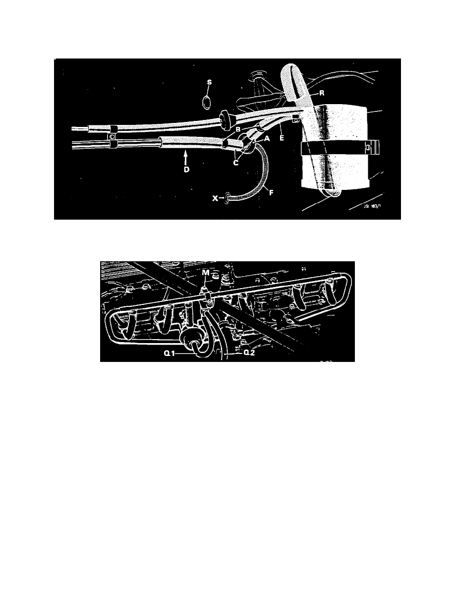
FIGURE 2 ILLUSTRATION OF COMPLETED CANISTER MODIFICATION
Illustration of Completed Canister Modification
FIGURE 3
PART B - FITTING THE THERMAL SWITCH
1.
Remove vacuum line from inlet manifold to fuel pressure regulator and discard.
2.
Secure the thermal switch, M, to the fuel rail as shown in Fig. 3.
3.
Connect the vacuum lines supplied in the kit in the following manner: Inlet manifold to thermal switch, Q-2, and thermal switch to fuel pressure
regulator, Q-1.
Claims
Warranty claims must be submitted quoting F 282 in the comment box. The following repair operation and time is applicable:
17.15.71 - Fit Hot Start Modification - 0.90 hrs.
KIT PARTS LIST_
Qty.
A.
- Vac valves 1
B.
- Reducers 2
C.
- Adaptor hoses (2.5" length) 2